


 91Likes
RC Crew Chief Software
 12-26-2018 | 07:58 PM
#751

just take your car to the track and tune your car there the software will never duplicate track conditions
 12-26-2018 | 08:58 PM
#752
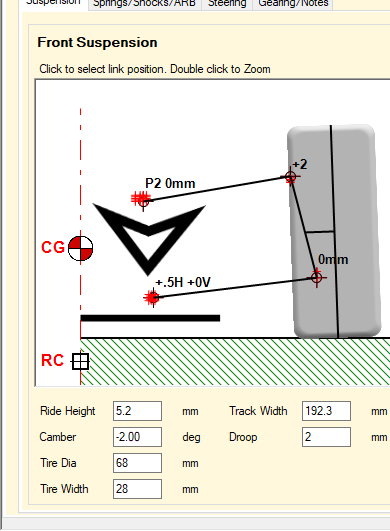
You are looking at all of the potential suspension settings on your T4. If you use the zoom feature, you will see in better detail each of the individual adjustment points. With these you can adjust camber, camber gain, and roll center.
12-27-2018 | 04:56 AM
#753
The points represent the different position for the hinge pin inserts. If you double click the image you can zoom in to see more detail. You can also add more points using the chassis manager.
12-27-2018 | 05:28 AM
#754
 12-27-2018 | 08:16 AM
#755
The default points represent all the positions for the front and rear blocks assuming the pin is located in the same location front and rear. If you are using different blocks for the front/rear then you need to add new position to represent the midpoint of the hinge pin using the chassis manager. The image below shows how the points have been named in the model. There are youtube videos on the website that show how to enter new points for a model.

03-18-2019 | 08:09 AM
#756
Tech Fanatic
iTrader: (1)
Joined: Jul 2014
Posts: 886
From: Hong Kong
Hi Bob
Have been taking a look at modelling an FF car into RC3. The motor overhangs the front. Does the application take this in to account? I'm finding the output from the app a bit confusing and not matching real world.
Have been taking a look at modelling an FF car into RC3. The motor overhangs the front. Does the application take this in to account? I'm finding the output from the app a bit confusing and not matching real world.
03-18-2019 | 10:26 AM
#757
That said if you consider the motor torque as a constant between setups then as you make setup changes the "relative" effect should be valid.
03-18-2019 | 10:50 AM
#758
Tech Regular
Joined: Jul 2017
Posts: 309
See here:
04-03-2019 | 02:30 PM
#760
If I remember correctly from the shock dyno testing that the RC3 model was validated against the performance difference between a vented and unvented shock cap was negligible. That is why I didn't include it in the model. The pressure in the chamber just doesn't change that much. In full scale gas pressurized shocks the purpose of the pressurized nitrogen is to increase the operating pressure of the shock to avoid the shock oil from vaporizing on the low pressure side of the piston when moving at high speed. When that happens the oil turns into an emulsion of oil and oil/air bubbles which makes the normally incompressible oil into a compressible one. Not a good thing normally but then the offroad guys depend on that happening in their shocks to provide the volume compensation needed.
04-03-2019 | 03:45 PM
#761
Tech Regular
Joined: Jul 2017
Posts: 309
Increasing the volume of the chamber above the bladder would reduce the pressure change in the air chamber above the shock bladder. Try it and see what happens. Doubtful you will see much change though.
If I remember correctly from the shock dyno testing that the RC3 model was validated against the performance difference between a vented and unvented shock cap was negligible. That is why I didn't include it in the model. The pressure in the chamber just doesn't change that much. In full scale gas pressurized shocks the purpose of the pressurized nitrogen is to increase the operating pressure of the shock to avoid the shock oil from vaporizing on the low pressure side of the piston when moving at high speed. When that happens the oil turns into an emulsion of oil and oil/air bubbles which makes the normally incompressible oil into a compressible one. Not a good thing normally but then the offroad guys depend on that happening in their shocks to provide the volume compensation needed.
If I remember correctly from the shock dyno testing that the RC3 model was validated against the performance difference between a vented and unvented shock cap was negligible. That is why I didn't include it in the model. The pressure in the chamber just doesn't change that much. In full scale gas pressurized shocks the purpose of the pressurized nitrogen is to increase the operating pressure of the shock to avoid the shock oil from vaporizing on the low pressure side of the piston when moving at high speed. When that happens the oil turns into an emulsion of oil and oil/air bubbles which makes the normally incompressible oil into a compressible one. Not a good thing normally but then the offroad guys depend on that happening in their shocks to provide the volume compensation needed.
Speaking of spring rates, I've been doing some multi-point spring measurements and have found that even so-called 'linear' springs have a varying rate across their travel. Would multi-rate springs be something that could work in a future version of RC3?
04-04-2019 | 05:08 AM
#762
The gas chamber volume has to be very small to get a large enough pressure change for the pneumatic spring effect to become significant. That said if you increase the shock Hc value by a factor of 10 will produce constant pressure at near atmospheric in the air pocket. That will eliminate any pneumatic spring.
If you haven't already you should check out the shock dyno testing that Icecyc1 did. He tested hole sizes/number, oil viscosity, bladders, different piston geometries..... Very interesting work. RC Shock Dyno Test Results.
I have thought about including progressive spring rates but it adds a whole other level of complexity. It makes everything dependent on the displacement of the spring. For example the roll stiffness would have a fixed value at zero displacement with a small factor increasing the rate as the spring is compressed.
I'm not surprised that linear springs are not 100% linear. I plan to investigate this as well in the near future.
06-05-2019 | 06:12 AM
#763
RC Crew Chief Version 4.3.2 has been released. The update will install automatically the second time you open the program. Once again this is a free update for licensed users.
Highlights:
1. Importing car models is now enabled during the 30 day trial period.
2. Added Setup Chart feature that graphically displays the magnitude and effect of setup changes compared to a selected setup.
3. Graphing of I2R motor power losses (what generates the heat) is now included in the acceleration simulation.
4. New calculator added to determine the center of flat top ball studs.
5. The point being edited in Chassis Manager Suspension position tables is now highlighted in the graphic display.
6. In the Motor Manager Dyno Analysis section the ability to graph RPM, Voltage and Current vs time has been added.
This short video highlights the improvements.
https://youtu.be/UAebnmwFtm8
06-21-2019 | 04:02 AM
#765
ATM the only thing that shows improved stability in the chart is front Kickup/Caster. Changing front/rear toe and shock oil or pistons would also change stability, I just haven't figured out how to quantify it relative to other changes yet. This is a work in progress so I will include more interactions in future updates.