


 8Likes
Lap Timing Decoder
 10-30-2013 | 11:48 PM
#331
Tech Rookie
Joined: Oct 2013
Posts: 3
Thanks for your reply maeg,
I know that the transponders work with AMB as well.
How long have you made your loop?
Our track is 10m wide, so the loop wire will have to be 20m long.
Howard, Would the amplifier and decoder be able to work on such a long loop?
Is anyone already using the system sucsessfully with such a long loop?
I know that the transponders work with AMB as well.
How long have you made your loop?
Our track is 10m wide, so the loop wire will have to be 20m long.
Howard, Would the amplifier and decoder be able to work on such a long loop?
Is anyone already using the system sucsessfully with such a long loop?
 10-31-2013 | 12:23 AM
#332
Tech Apprentice
Joined: Aug 2013
Posts: 52
Thanks for your reply maeg,
I know that the transponders work with AMB as well.
How long have you made your loop?
Our track is 10m wide, so the loop wire will have to be 20m long.
Howard, Would the amplifier and decoder be able to work on such a long loop?
Is anyone already using the system sucsessfully with such a long loop?
I know that the transponders work with AMB as well.
How long have you made your loop?
Our track is 10m wide, so the loop wire will have to be 20m long.
Howard, Would the amplifier and decoder be able to work on such a long loop?
Is anyone already using the system sucsessfully with such a long loop?
 11-06-2013 | 11:31 PM
#336
Do we have a CLPD yet?
And if we do can I get a copy of the programming or a chip.
I can hand solder most surface mount devices over .05 but prefer .08 64pinTQFP.
I have been watching this project from day one and I am really impressed with the progress. At one point I was thinking of using a Xmega for the decoder but even at 48Mhz and in machine language the Xmega would be to slow and the TTL chip solution is a great idea but to big for my taste. The CLPD is the way to go ,I would rather spend $25.00 for one chip then point to point solder 15+ chips.
The Arduino shield is a neat idea for Hobby level designs but I would rather develop my own hand held timing system in a 2 chip solution that would output AMB compatable packets. then I can use one of the many timing systems that are out there.
11-17-2013 | 07:52 AM
#337
Tech Initiate
Joined: Jun 2013
Posts: 20
Later this year I'll be implementing the whole thing in an FPGA with multiple channels, event timestamping and data buffering. First I'm trying to simplify the input amplifier.
12-29-2013 | 12:58 PM
#338
Tech Initiate
Joined: Apr 2013
Posts: 46
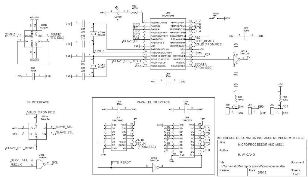
Here’s the schematic I promised earlier:
The microprocessor receives transponder data (stripped of the first two bytes by the Preamble Detector / Stripper, or PDS), timestamps it, and transmits the result as ASCII hexadecimal characters in asynchronous serial format to an external computer.
(Alternatively, I have also created software that recognizes a single transponder and calculates lap times for it, for use in testing and as a “Personal Lap Timer”.)
Microprocessor U60 runs at 20 MHz, as determined by crystal XTL60 and capacitors C65 and C66. (U60 is shown as a 28 pin PIC16F886; my prototype uses the 40 pin PIC16F887.) One of the internal counters runs at 32.00 KHz, as determined by crystal XTL61 and capacitors C67 and C68. This is used as a timebase for the timestamps.
U61B divides the 20 MHz clock down to 10 MHz for use in the Synchronous Serial Converter (SSC). (Thanks to Brano, “OM2KW”, for pointing out that the PIC oscillator will drive the counter when in HS mode.)
The prototype currently transfers the transponder data into the microprocessor using the components labeled “Parallel Interface”. When the code for the SPI interface is complete, these will be eliminated , and U61A and U41D will serve the purpose.
EDIT: For the latest schematics, see post 206:
http://www.rctech.net/forum/12118142-post206.html
Is it possible to give the SPI signal characteristic ?
number of bit, parity, SPI mode, clock polarity, data is capture on clock's rising edge or falling edge ?
Thanks.
Last edited by luluFRA; 12-29-2013 at 02:10 PM.
12-30-2013 | 04:21 AM
#339
http://www.rctech.net/forum/radio-el...l#post11880840
Data should be captured in on the positive-going edge of SSCLK, or the negative-going edge of /SSCLK.
The schematic you show was for a previous hardware revision, which created a slave select signal and gated clock for the PIC microprocessor. In this case, data should be captured on the positive-going edge of SCL.
There is no particular number of bits. The bits are presented serially with no delays between bytes, words, or any other groupings. The data stream will continue as long as valid data is received. Since there is no particular grouping of bits, there is also no parity bit.
It is up to you to determine what operating mode on your microprocessor will support the data stream presented to it.
On a related note, I recently heard from Microchip regarding the problems I had with their SPI module. I had previously posted that I could not get their module to work when running at the maximum serial clock frequency specification, despite all timing requirements being met. Microchip has confirmed the problem. I'm sure it will take a new silicon revision to fix it, but I don't think that's in their agenda, since the current silicon has existed for quite a while, and I was the first one to report the problem to them.
Last edited by howardcano; 12-30-2013 at 04:31 AM.
01-13-2014 | 12:29 AM
#340
Tech Apprentice
Joined: Aug 2013
Posts: 52
Hello Howard!
Our winter season is in hot time.
Could you explain, please, about capacity of loop?
We have some problems with signal quality, Payalneg added to the firmware option to display signal quality for each time it detects transpoder - so now I can see it on track in real time.
I need to tune my loop better. The only thing I can try - is changing wire of the loop and capacity.
Maybe some rules for changing capacity? When I need to take bigger capacitor or smaller?
01-14-2014 | 04:42 PM
#341
Hello Howard!
Our winter season is in hot time.
Could you explain, please, about capacity of loop?
We have some problems with signal quality, Payalneg added to the firmware option to display signal quality for each time it detects transpoder - so now I can see it on track in real time.
I need to tune my loop better. The only thing I can try - is changing wire of the loop and capacity.
Maybe some rules for changing capacity? When I need to take bigger capacitor or smaller?
Our winter season is in hot time.
Could you explain, please, about capacity of loop?
We have some problems with signal quality, Payalneg added to the firmware option to display signal quality for each time it detects transpoder - so now I can see it on track in real time.
I need to tune my loop better. The only thing I can try - is changing wire of the loop and capacity.
Maybe some rules for changing capacity? When I need to take bigger capacitor or smaller?
http://www.rctech.net/forum/12222187-post251.html
In general, a larger loop will require less capacitance to keep it resonant at about 5 MHz.
You can verify that the tuning is correct by monitoring the output of the loop amplifier (R11 pin 2) using an oscilloscope with AC coupling. Place a transponder above the center of the loop, high enough to reduce the loop amplifier output to about 10mV peak to peak, then adjust the loop capacitance for maximum carrier output.
 01-21-2014 | 11:48 PM
#343
Tech Master
Joined: May 2008
Posts: 1,505
From: Los Angeles
I have encountered the same problem two races in a row now... Everything works great all day long and then at about the 11-12th hour of my race program... Mylaps RC4 Decoder box is not taking in anymore laps. If i reboot the box it starts working again... I have been tempted to clear passing on the box but figure it would be much better to ask here- I really only mess with the squelch on the box-
What is going wrong...
Also what if any maintenance to the box is needed?
Thanks guys!
What is going wrong...
Also what if any maintenance to the box is needed?
Thanks guys!
01-22-2014 | 05:22 AM
#344
I have encountered the same problem two races in a row now... Everything works great all day long and then at about the 11-12th hour of my race program... Mylaps RC4 Decoder box is not taking in anymore laps. If i reboot the box it starts working again... I have been tempted to clear passing on the box but figure it would be much better to ask here- I really only mess with the squelch on the box-
What is going wrong...
Also what if any maintenance to the box is needed?
Thanks guys!
What is going wrong...
Also what if any maintenance to the box is needed?
Thanks guys!
The disadvantage in posting here is that this thread is not about the RC4 decoder, so you may not get many responses.
02-08-2014 | 06:19 AM
#345
Tech Rookie
Joined: Aug 2013
Posts: 1
I could see potential interest from other forms of racing (ie. auto, motocycle, etc) if the loop could accomodate greater lengths and transponders could send greater distances.

