


 19Likes
Project: Break in Dutch machine
 01-08-2016, 04:23 AM
#1

The talk on these forums:
http://www.rctech.net/forum/onroad-n...eak-dutch.html
http://www.rctech.net/forum/offroad-...ak-method.html
I know the guy behind this and we have talked a lot so he did convince me to give it a try. Because I am a guy of re-useing stuff and build cheap I had an old window wiper motor as a base for this project.
I also had another look on the design, he had an hole at the side to connect the shaft, that needs to be fluid tight, with a hole on top there is no need to think about that. He also uses several heaters in the oil, I want to heat the engine directly on top of the sleeve, that will give much faster the heat in the engine and I think less power is needed.
And last of all I want to have it small and on on 12v so I can take it and use it anywhere.
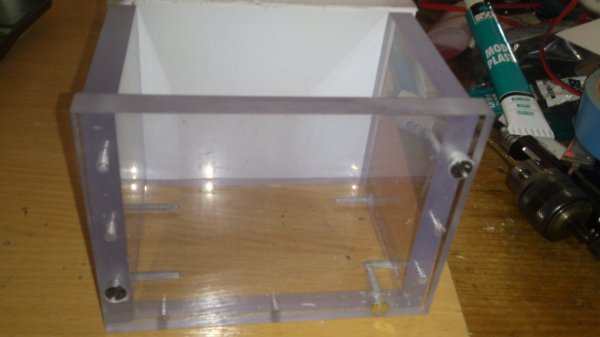
I managed to get some 10mm thick lexan cut to the right size at the local plastics shop.
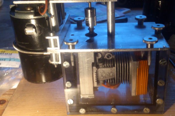
The "bathtub" made with 10mm thick lexan. It is glued with a silicone glue and screwed to make it strong.
Rough setup with a car window wiper motor
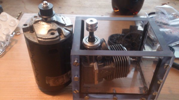
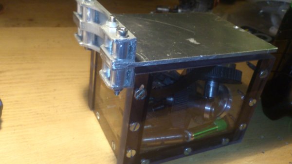
It Becoms a small and portable design
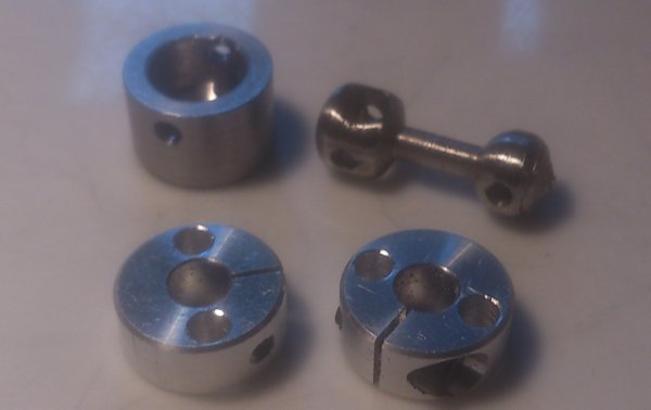
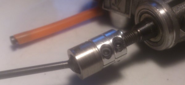
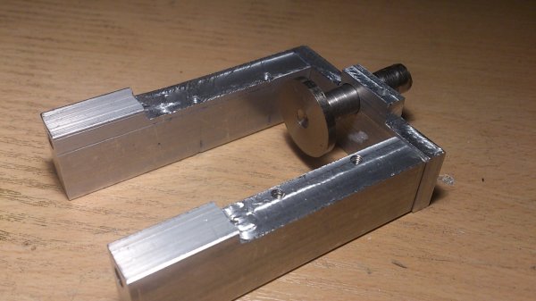
The 5mm clamps and a home made short CVD shaft to connect the crankshaft
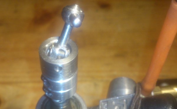
It does fit a MRX5 front shaft as well
With my short shaft
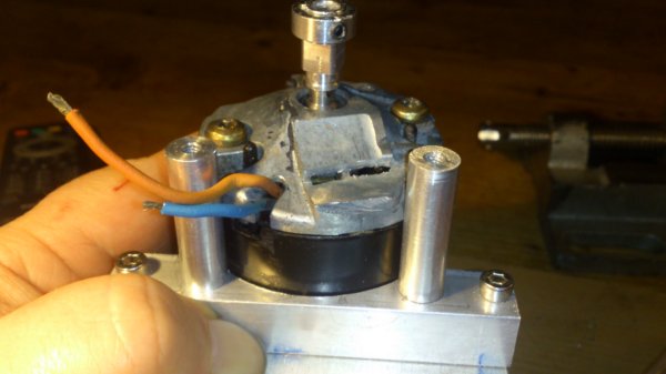
Engine mounts
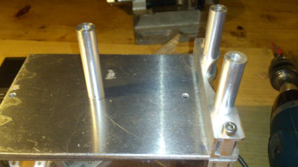
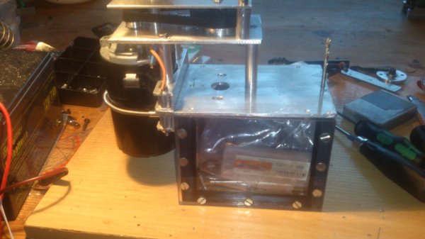
The beginning of the cap over the box, this will be the window wiper motor mount
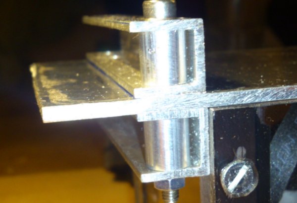
Made it fit on a rotation table on the mill
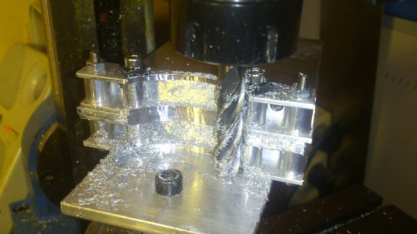
Nice 60mm rounding to fit the motor
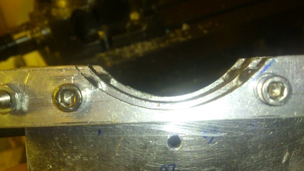
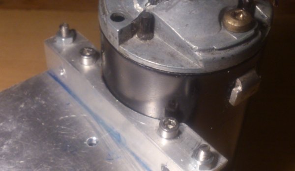
Total fit on the box
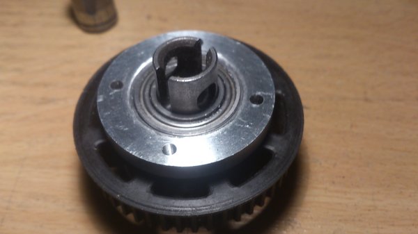
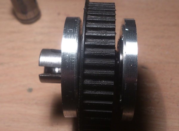
An old MRX5 rear shaft and pulley will be used to get a shaft connection above the crank shaft. 2 fresh bearing holders were made.
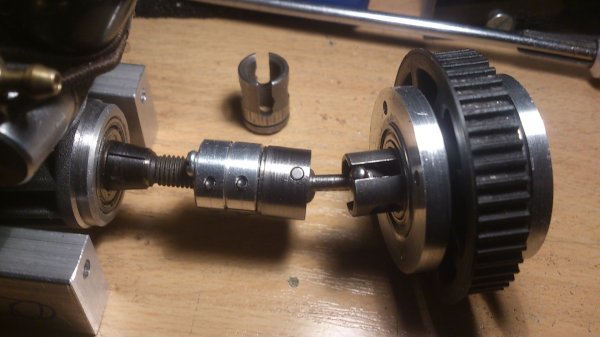
Cut off one side of the shaft
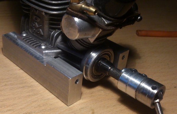
A total overview of the crankshaft connection
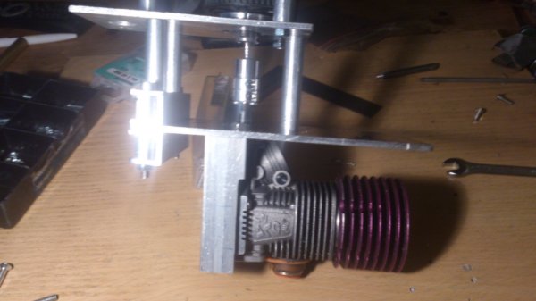
Time to mount the pulley with shaft on top of the cap.
Again, the motor will fit nice, on the shaft a Mugen MRX4 pulley adapter for a 16t pulley.
A short overview, an 78 tooth timing belt of a starter box is used to get the right distance
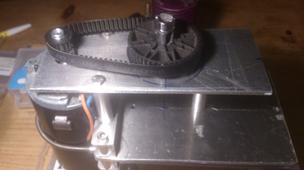
Fits nice
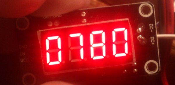
An RPM sensor to keep control on the used rpm, a small magnet is pressed in the pulley.

It works.
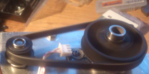
almost 800 RPM
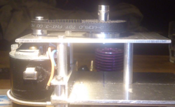
An overview of the total building og the cap.
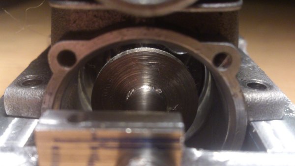
Because the engine is fully open the conrod needs to be held on its place to make it universal an adjustable disc will be used.
A look from the rear in the engine
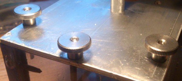
The cap will be mounted with some thumb nuts (not home made)
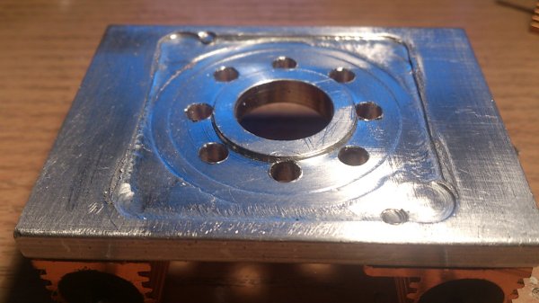
The heater plate which will be mounted on the place of the button head
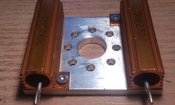
2x huge 50w resistors will be used as heaters directly in contact with the engine sleeve.
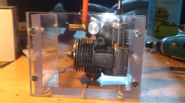
Another total overview
The start of the controll panel. It will contain a PWM motor controler, a temperature controler, a RPM meter and a current meter which will monitor the window wiper motor in the hope to see the current going down during the break in proces.
I had an idea for nice buttons for the temperature controler but this works fine.

So far the building, in the next weeks I hope to finish it and make it work.
http://www.rctech.net/forum/onroad-n...eak-dutch.html
http://www.rctech.net/forum/offroad-...ak-method.html
I know the guy behind this and we have talked a lot so he did convince me to give it a try. Because I am a guy of re-useing stuff and build cheap I had an old window wiper motor as a base for this project.
I also had another look on the design, he had an hole at the side to connect the shaft, that needs to be fluid tight, with a hole on top there is no need to think about that. He also uses several heaters in the oil, I want to heat the engine directly on top of the sleeve, that will give much faster the heat in the engine and I think less power is needed.
And last of all I want to have it small and on on 12v so I can take it and use it anywhere.
I managed to get some 10mm thick lexan cut to the right size at the local plastics shop.
The "bathtub" made with 10mm thick lexan. It is glued with a silicone glue and screwed to make it strong.
Rough setup with a car window wiper motor
It Becoms a small and portable design
The 5mm clamps and a home made short CVD shaft to connect the crankshaft
It does fit a MRX5 front shaft as well
With my short shaft
Engine mounts
The beginning of the cap over the box, this will be the window wiper motor mount
Made it fit on a rotation table on the mill
Nice 60mm rounding to fit the motor
Total fit on the box
An old MRX5 rear shaft and pulley will be used to get a shaft connection above the crank shaft. 2 fresh bearing holders were made.
Cut off one side of the shaft
A total overview of the crankshaft connection
Time to mount the pulley with shaft on top of the cap.
Again, the motor will fit nice, on the shaft a Mugen MRX4 pulley adapter for a 16t pulley.
A short overview, an 78 tooth timing belt of a starter box is used to get the right distance
Fits nice
An RPM sensor to keep control on the used rpm, a small magnet is pressed in the pulley.
It works.
almost 800 RPM
An overview of the total building og the cap.
Because the engine is fully open the conrod needs to be held on its place to make it universal an adjustable disc will be used.
A look from the rear in the engine
The cap will be mounted with some thumb nuts (not home made)
The heater plate which will be mounted on the place of the button head
2x huge 50w resistors will be used as heaters directly in contact with the engine sleeve.
Another total overview
The start of the controll panel. It will contain a PWM motor controler, a temperature controler, a RPM meter and a current meter which will monitor the window wiper motor in the hope to see the current going down during the break in proces.
I had an idea for nice buttons for the temperature controler but this works fine.
So far the building, in the next weeks I hope to finish it and make it work.
 01-08-2016, 04:21 PM
#3
Now that's something I like to see! A bit too complicated in the coupling, could you machine this but with one less transfer?
 01-09-2016, 02:31 AM
#6
The short CVD axle is made so there is no need for a precise position of the engine in line with the shaft above.
Mounting a pulley direct on the crankshaft will give a huge sidewards load on the engine bearings so that is no good idea either.
And yes, with no plug and heated up to about 85~90 degrees (operating temp on the track) it is much easier to turn the engine arround. The 1:3 pulley ratio will also help to make it a little bit easier for the window wiper motor.
01-09-2016, 04:21 AM
#7
This is excellent, i recall you mentioning you were going to be working on something more portable when the first pics/vids surfaced of this process,
cant wait to see it up and running and hear about your results.
This little gadget could pop up at tracks and in workshops all over the place esp with it being simple to cart around and setup im assuming.
Im curious to know how long you think the process will take to break in a fresh engine or is this yet to be confirmed? Either way great work and smart thinking.
01-09-2016, 09:23 AM
#8
I know all the information of what is needed to break in an engine on this stand although I think there is more to investigate. The original break-in Dutch is using a high performance synthetic 2-stroke oil but what about hone oil or other oils, as example I did find a special thin SAE20 spec break in oil.
http://lucasoil-motor.com/en/high-zi...807106263.html
But so far I was told good results can be made with at least 4 hours running also depending the rate of pinch. I was also told about an engine running for 2 days...
Most important is that the 1st real start on the track must still be carefully done because the piston will get some real heat and expands more. Also due the heat there will be a grow bringing back some cold pinch.
I think with 2 tanks on the track slowly building up the performance with maybe a small heatcycle between them it must be enough to have it race ready.
01-10-2016, 12:49 PM
#9
It needs an open backplate to prevent an hydro lock and it also need to support the conrod so it will stay on the crank pin. Many brands and model engines arround with all different dimension back plates. Time to make an universal back plate.
The 2 parts
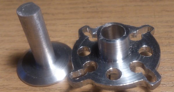
How it will be mounted in the engine
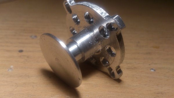
A clamp construction will keep the support disc on its place

Enlarged mouting holes for different crank cases (sadly my rotation table has some play)

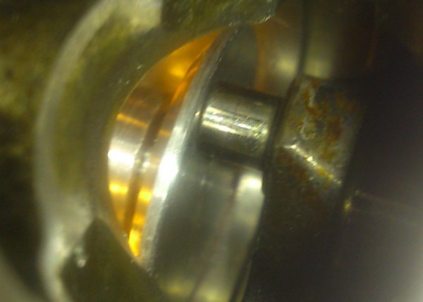
A look inside the engine
The 2 parts
How it will be mounted in the engine
A clamp construction will keep the support disc on its place
Enlarged mouting holes for different crank cases (sadly my rotation table has some play)
A look inside the engine
01-13-2016, 03:17 PM
#10
Tonight I have done a little bit.
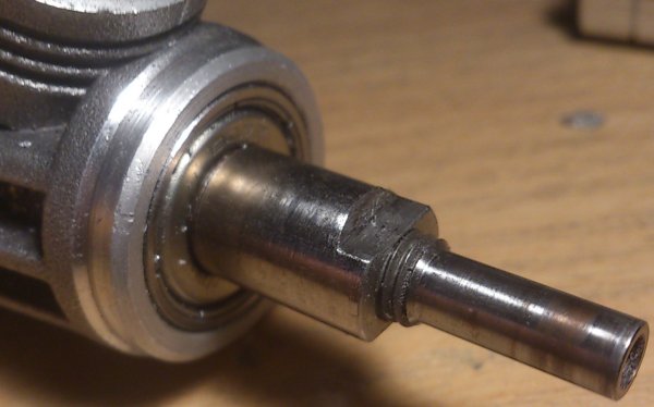
A nut to lock the crankshaft on the front bearing so it will stay on its place. I had to borrow the 1/4-28 thread tool to make the screw thread.

Mounted:
I have mounted all resistors an wired them. Within 10 minutes this is the side of the crank case. At this moment the resistors are about 150 degrees. Finally in oil the heat will be more equal spreaded (I hope).

A nut to lock the crankshaft on the front bearing so it will stay on its place. I had to borrow the 1/4-28 thread tool to make the screw thread.
Mounted:
I have mounted all resistors an wired them. Within 10 minutes this is the side of the crank case. At this moment the resistors are about 150 degrees. Finally in oil the heat will be more equal spreaded (I hope).
01-16-2016, 09:50 AM
#11
Today I made a PWM controler for the electric motor. I had a base diagram and modified it for the use with the needed RPM range and so far so good. I only need to get rid of the beeping noise but that is just a simple frequency change.
| + YouTube Video | |
01-17-2016, 12:02 PM
#12
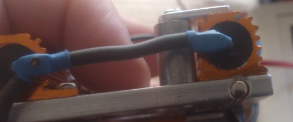
The temperature sensor is drilled in the heater plate on the right just under the resistor.
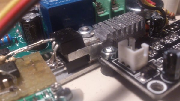
The PWM controler, because of the small space it could not be any larger. The beep is gone with a 10 times higher frequency but the control range was changed a bit so I had to modify it again.
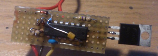
Sadly one FET becomes too hot, I "piggy banked" a second. Also made a fitting heatsink from a 10x10 bar of aluminium.
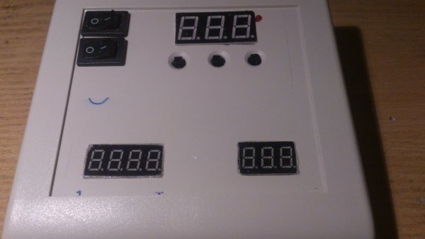
The control panel.

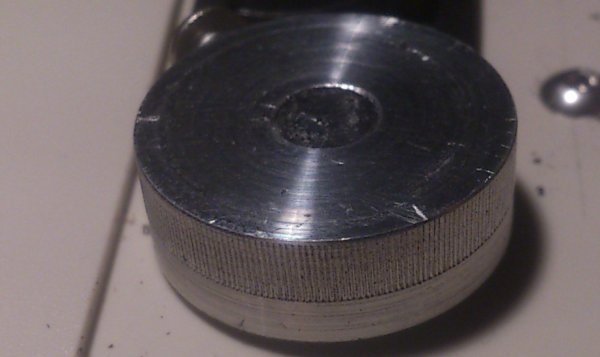
Made a low profile knob.
Now it is time for the wirering with connectors between break in stand and control panel.
The PWM controler, because of the small space it could not be any larger. The beep is gone with a 10 times higher frequency but the control range was changed a bit so I had to modify it again.
Sadly one FET becomes too hot, I "piggy banked" a second. Also made a fitting heatsink from a 10x10 bar of aluminium.
The control panel.
Made a low profile knob.
Now it is time for the wirering with connectors between break in stand and control panel.
01-18-2016, 02:51 PM
#13
The controler on the internal side wired:
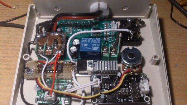
And it works.

And it works.
01-22-2016, 03:00 PM
#14
I wanted a connector between the controler and the break-in stand. I used a standard 25 pole DSUB connector but gold plated. I can use 5 amps a pin so with some pins parallel it is easy to connect the power. In the search of how to mount the connector I came to this.
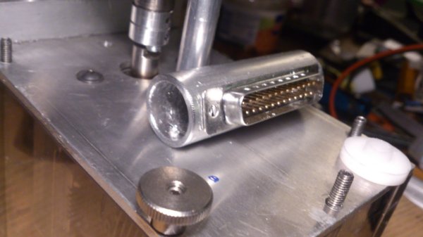
Made a small PTFE plug to hold the cables coming from the inside.

Placed the connector and used some kit on the wires coming from the inside.
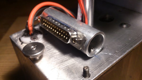
The other connector just goes over the nut

All finished
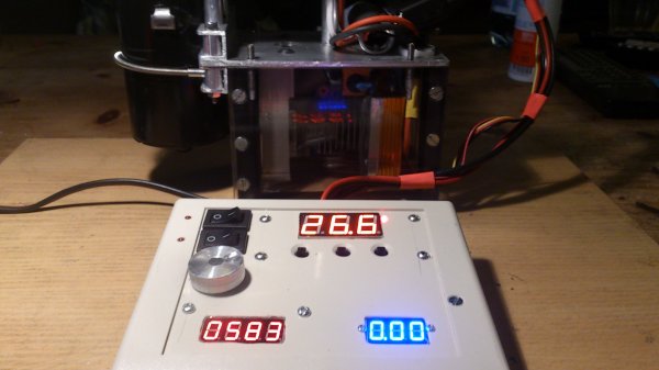
And in function
The large meter on the top is the temperature, the 3 small buttons right below it are to set the temperature and many other settings. The 4 digit meter on the left is a RPM meter. The blue meter is a current meter only on the motor, this will be an indicator of how far the pinch is taken away. The large knob is setting the RPM and the 2 switches are to switch on/of the motor and the heater.
Now I have to create a tube to fill the oil and a seal between the box and the cap, that will be cut out from a cheap silicone bake mat.
Made a small PTFE plug to hold the cables coming from the inside.
Placed the connector and used some kit on the wires coming from the inside.
The other connector just goes over the nut
All finished
And in function
| + YouTube Video | |
The large meter on the top is the temperature, the 3 small buttons right below it are to set the temperature and many other settings. The 4 digit meter on the left is a RPM meter. The blue meter is a current meter only on the motor, this will be an indicator of how far the pinch is taken away. The large knob is setting the RPM and the 2 switches are to switch on/of the motor and the heater.
Now I have to create a tube to fill the oil and a seal between the box and the cap, that will be cut out from a cheap silicone bake mat.
01-22-2016, 03:28 PM
#15
Excellent work