


 45Likes
Rotor Master


 09-08-2023 | 10:16 PM
#47
Love the new software with the positive and negative displayed. The colored case is also a delightful edition. May even take it to the track tomorrow and advertise to some California racers😎. Awesome gentlemen to deal with as well.
 09-11-2023 | 05:57 AM
#50
I'll update the BOM in my github. For some reason I must have removed the bom I created and only the Kicad generated bom is there.
EDIT: I updated my BOM in Github. BOM.xlsx
Last edited by trilerian; 09-11-2023 at 06:20 AM.
09-18-2023 | 01:35 PM
#51
I finally had a chance to mess around with this thing. This is awesome. I see why you relocated the mount. The slightest pressure on it will mess up the readings. For accuracy, my the factor reading, for my certified Slot Machine was 1775 and the reading from your Rotor Master was 1772. You were right about how strong the Surpass Rocket V6 rotors are. They averaged 1779 for the stock spec and 1773 for the Lite Weight.
Here's a thought. When lining up the rotor, I find it a pain to have to add shims to get it right. Especially when you're doing multiple rotors. Is it possible to design an adjustable back plate to butt the end of the rotor up to? Something threaded so it can be fine-tuned to be where you need it, or even a slider would be nice.
Here's a thought. When lining up the rotor, I find it a pain to have to add shims to get it right. Especially when you're doing multiple rotors. Is it possible to design an adjustable back plate to butt the end of the rotor up to? Something threaded so it can be fine-tuned to be where you need it, or even a slider would be nice.
09-18-2023 | 01:58 PM
#52
I finally had a chance to mess around with this thing. This is awesome. I see why you relocated the mount. The slightest pressure on it will mess up the readings. For accuracy, my the factor reading, for my certified Slot Machine was 1775 and the reading from your Rotor Master was 1772. You were right about how strong the Surpass Rocket V6 rotors are. They averaged 1779 for the stock spec and 1773 for the Lite Weight.
Here's a thought. When lining up the rotor, I find it a pain to have to add shims to get it right. Especially when you're doing multiple rotors. Is it possible to design an adjustable back plate to butt the end of the rotor up to? Something threaded so it can be fine-tuned to be where you need it, or even a slider would be nice.
Here's a thought. When lining up the rotor, I find it a pain to have to add shims to get it right. Especially when you're doing multiple rotors. Is it possible to design an adjustable back plate to butt the end of the rotor up to? Something threaded so it can be fine-tuned to be where you need it, or even a slider would be nice.
09-18-2023 | 03:09 PM
#53
How would it interfere with the tolerances? It's just helps keep the rotor from moving side to side. Shimming takes too long.
09-18-2023 | 03:19 PM
#54
Given how the Hobbywing rotor barely fits on there while other rotors need the gap, the part that moves will likely need to be the part the rotor directly rests on, rather than having a separate stopper. More parts means more interfaces that have tolerances. Depending on the design there could be additional tolerances related to friction, or fastener tension distorting the material etc. In short, more parts and more complexity means more chances for tolerance issues to pop up.
09-18-2023 | 04:18 PM
#56
09-18-2023 | 05:29 PM
#57
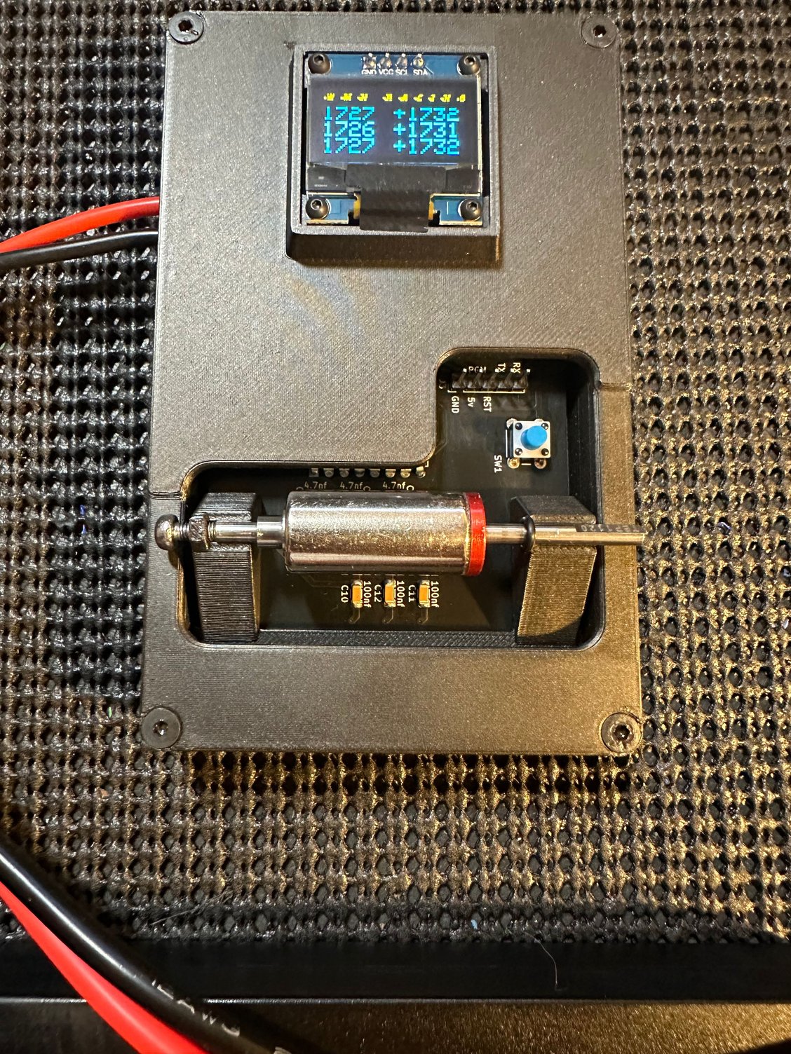
Like I said, low tech solution. Any type of sliding mount will add variance to the readings. So this still allows for a solid base. Also note the o ring on the right side of the shaft up against the mount. I have been using an o ring lately, this helps with small movement.

09-19-2023 | 12:09 PM
#58
Like I said, low tech solution. Any type of sliding mount will add variance to the readings. So this still allows for a solid base. Also note the o ring on the right side of the shaft up against the mount. I have been using an o ring lately, this helps with small movement.
That's the design I was thinking of, but with a plastic screw so it doesn't interfere with the magnet strength.
09-19-2023 | 01:30 PM
#59
I used an aluminum screw. But... I am going to make a modification to this. I am going to integrate a 3d printed part on the case itself not the rotor holder. But time...
09-19-2023 | 07:56 PM
#60