


 45Likes
Rotor Master
 08-20-2023 | 09:07 PM
#16
 08-20-2023 | 11:45 PM
#17

In what way are they heading in that direction? They've been in the ~1850 upper limit ballpark for years. The rules limit their dimensions and material, which is a pretty big constraint to magnetic strength.
08-21-2023 | 06:04 AM
#18
My point is that things will eventually progress, and theres mod rotors that already go beyond 2000 strength so a tool that cant measure that is not great. Its nice to track even your mod rotors strength so that motor ever gets hot you can check the rotor strength and see if its hurt. But more importantly having a tool that can do say 2500 accurately now would be useful for years to come giving you a baseline now.
08-21-2023 | 06:08 AM
#19
Personally I think a tool with an accurate range of 1000-2500 would be perfect for any 1/10 application right now and for years to come. I applaud trilerian for designing it and basically showing us how to build our own fairly easily. With some hopefully easy tweaks it could be much better. Like I said I want to build one but it'd be much more useful with just a little more range.
08-21-2023 | 06:34 AM
#20
Not all the rotors were the max dimensions a year or so ago when a friend and I did some testing and motor tuning. And materials get refined all the time, so who knows when a stronger magnet will get relased.
My point is that things will eventually progress, and theres mod rotors that already go beyond 2000 strength so a tool that cant measure that is not great. Its nice to track even your mod rotors strength so that motor ever gets hot you can check the rotor strength and see if its hurt. But more importantly having a tool that can do say 2500 accurately now would be useful for years to come giving you a baseline now.
My point is that things will eventually progress, and theres mod rotors that already go beyond 2000 strength so a tool that cant measure that is not great. Its nice to track even your mod rotors strength so that motor ever gets hot you can check the rotor strength and see if its hurt. But more importantly having a tool that can do say 2500 accurately now would be useful for years to come giving you a baseline now.
Mod rotors have already been covered as a reason to have a different version, but that's separate to this being useful for stock rotors.
08-21-2023 | 07:24 AM
#21
Personally I think a tool with an accurate range of 1000-2500 would be perfect for any 1/10 application right now and for years to come. I applaud trilerian for designing it and basically showing us how to build our own fairly easily. With some hopefully easy tweaks it could be much better. Like I said I want to build one but it'd be much more useful with just a little more range.
These units, mine included use a sensor that measures the change of the output of the hall effect sensor. This change is in millivolts. The sensors we use have a sensitivity of 1.3mv/gauss. They have a range of 0.55v-4.50v, with a quiescent output of appx 2.5v. So that is basically a 2000 mv range. 2000/1.3 = 1538 gauss. To get the best resolution, I have the rotor as close to the sensors as I can to achieve the common readings of spec motors.
Another option is to use a sensor with 0.5mv/gauss sensitivity. I do have some of these and have made a unit with them. They will be less accurate, but you can get readings of 4000 gauss using them.
08-21-2023 | 09:08 AM
#23
Thanks.
Edit: Obviously that is a complete redesign of the entire project, so it may take me a bit to get to.
Edit 2: As to filtering the output of the sensors. I'm glad you brought this up. I was originally planning on putting a low pass filter on the sensor outputs as the datasheet calls that out for the standard design. But after looking at the outputs on my scope I didn't see any difference in the output vs transient noise. This could be a limitation of the scope, considering mine is relatively cheap as far as oscilloscopes go. Regardless in my next design I was going to add a low pass filter to each sensor as well as another decoupling capacitor to each input, but I do think it is just throwing components there that are not really needed.
Last edited by trilerian; 08-21-2023 at 10:33 AM.
08-21-2023 | 09:49 AM
#24
Here�s the Amazon link to the case pictyfor anyone that purchases/builds one.
https://www.amazon.com/dp/B07QRFX94D...p_mob_ap_share
https://www.amazon.com/dp/B07QRFX94D...p_mob_ap_share
08-25-2023 | 09:00 AM
#25
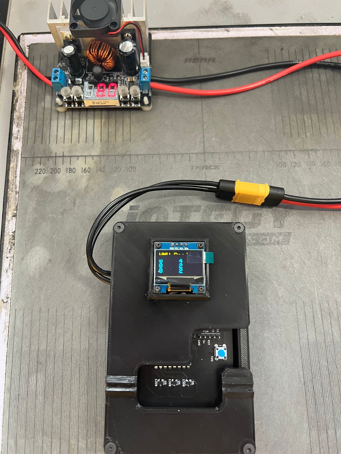
Finally life slowed down enough to play with the rotor checker. Another thing for guys to not have to worry about charging a pack to use during testing for this or your motor analyser is this lil power regulator thingy (can�t remember the exact name) Hooks to your power supply and you can set the voltage so tests are repeatable and aren't skewed should lipo voltage drop. Especially when tuning motors. This was about $20 shipped off Amazon. I�ve had this for quite a while so I don�t think I have the link saved. I while search and post it when I have more time later on.
08-25-2023 | 09:27 AM
#27
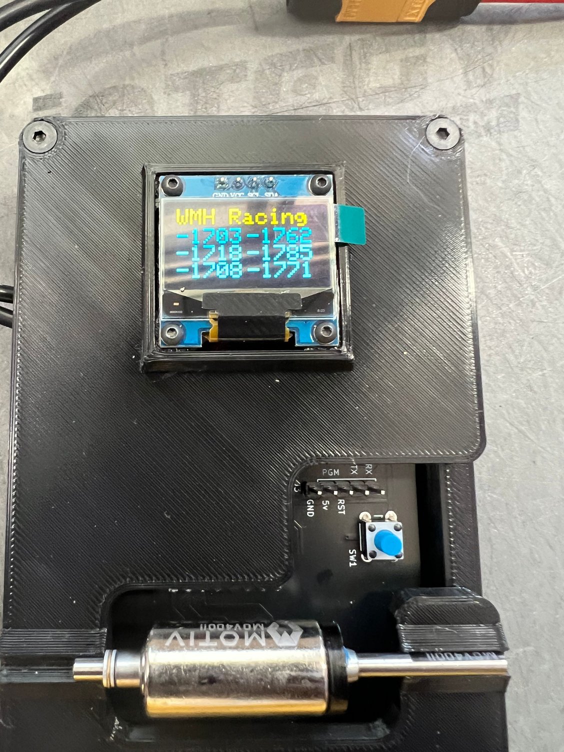
So comparing this to my Fantom the numbers don�t exactly match but what they both do consistently is give the same readings every time. The lower numbered rotor on my Fantom also showed to be the the lower rotor on this unit. I also like that the connecting plug was provided for me to wire up how I pleased.


08-25-2023 | 09:41 AM
#28
So comparing this to my Fantom the numbers don’t exactly match but what they both do consistently is give the same readings every time. The lower numbered rotor on my Fantom also showed to be the the lower rotor on this unit. I also like that the connecting plug was provided for me to wire up how I pleased.
Just curious, are you checking both plus and minus sides? I only see pics for the minus side. The plus side doesn't have a dash next to it.
I guess I probably should re write the code to make that more apparent. Add a + to the plus side readings.
08-25-2023 | 07:02 PM
#30