


 18Likes
Hobbywing Tunalyzer
 05-03-2023 | 11:59 AM
#16

Just got my Tunalyzer today. Comparing the same motor on both the SkyRC analyser and the Hobbywing Tunalyzer, the KV values are significantly different. 4100 vs 4600. Despite the battery voltage being at 8.4V and the Hobbywing regulates down to 7.4V, it records a higher RPM. Also the Bluetooth adaptor mode doesn't work with my G2S ESC, it drops out while reading the parameters. It seems to work on my 80A stock spec though.
I will add that I am planning on testing my Motolyser for correct Kv values this weekend. I just got my oscilloscope today so I need to work out exactly how I want to perform my test.
 05-03-2023 | 04:10 PM
#19
I'm curious if one unit is using the back emf voltage and the other is using the seen voltage by the device? They should be using the back emf voltage, and since they are most likely using that to calculate rpm, you would figure they would both use the back emf voltage as well. But it may have been an oversight in the programming. I don't know, just a guess.
I will add that I am planning on testing my Motolyser for correct Kv values this weekend. I just got my oscilloscope today so I need to work out exactly how I want to perform my test.
I will add that I am planning on testing my Motolyser for correct Kv values this weekend. I just got my oscilloscope today so I need to work out exactly how I want to perform my test.
05-03-2023 | 07:16 PM
#20
So... I've never used an oscilloscope before so this was kind of fun.
Testing steps:
1. Measure RPM of test motor while connected to my Motolyser II to verify accuracy of the rpm that the device reads.
2. Couple test motor to the motor we are wanting to determine the Kv
3. Ground one phase of the DUT and probe another with the oscilloscope
4. Take measurement of RMS voltage
5. Note the RPM of the test motor
6. Divide RPM of test motor by the RMS voltage of the DUT to find Kv of the DUT
7. Hook the DUT up to the Motolyser and get its measured Kv from it
I used a USGT motor as my test motor and an R1 v21s 21.5 as what I was trying to find the Kv of.
Kv from experiment was 2659
Kv from the motolyser was 2568
Now, the experiment was crude but fun. Also I expected a nice sine wave on the scope and got a jagged sine wave. Tried multiple motors with the same results. I am going to have to figure that out, but like I said, first time using a scope.
Now I would like to test a SKY RC and a Tunalyser. But...
EDIT: I ran the test again but this time using DC coupling on the channel and the Kv was almost spot on with the Motolyser. 2566
Last edited by trilerian; 05-03-2023 at 08:27 PM.
05-03-2023 | 08:35 PM
#21
So... I've never used an oscilloscope before so this was kind of fun.
Testing steps:
1. Measure RPM of test motor while connected to my Motolyser II to verify accuracy of the rpm that the device reads.
2. Couple test motor to the motor we are wanting to determine the Kv
3. Ground one phase of the DUT and probe another with the oscilloscope
4. Take measurement of RMS voltage
5. Note the RPM of the test motor
6. Divide RPM of test motor by the RMS voltage of the DUT to find Kv of the DUT
7. Hook the DUT up to the Motolyser and get its measured Kv from it
I used a USGT motor as my test motor and an R1 v21s 21.5 as what I was trying to find the Kv of.
Kv from experiment was 2659
Kv from the motolyser was 2568
Now, the experiment was crude but fun. Also I expected a nice sine wave on the scope and got a jagged sine wave. Tried multiple motors with the same results. I am going to have to figure that out, but like I said, first time using a scope.
Now I would like to test a SKY RC and a Tunalyser. But...
EDIT: I ran the test again but this time using DC coupling on the channel and the Kv was almost spot on with the Motolyser. 2566
05-03-2023 | 09:46 PM
#22
Coming up with a way to do this without a slave motor is going to be tricky. The back emf will have to be isolated from the supply voltage. I will have to do a lot more reading to figure this out.
05-03-2023 | 10:45 PM
#23
That thought had crossed my mind earlier in the day. Then I got home and the thrill of something new drove it from my mind... But you are correct, it will not take timing adjustments into consideration. Weird though that the timing on the motor just happened to be the right timing to make the test work.
Coming up with a way to do this without a slave motor is going to be tricky. The back emf will have to be isolated from the supply voltage. I will have to do a lot more reading to figure this out.
Coming up with a way to do this without a slave motor is going to be tricky. The back emf will have to be isolated from the supply voltage. I will have to do a lot more reading to figure this out.
05-04-2023 | 05:30 AM
#24
From everything I have read, Kv actually comes from the back emf. The back emf voltage will be slightly lower than the supply voltage due to the winding resistance and some other small factors. My understanding is that motors that are rated at a Kv value are measured this way. I guess I was just trying to come up with a way to measure the actual back emf and see if that is what these devices use. But the Motolyser gives the test voltage so I can just compare that. But now, I still want to see the actual back emf.
05-04-2023 | 06:20 AM
#26
And again, from the research I have done, Kv is measure from the rpm / bemf. Generically it is given as rpm / supply voltage because that is easier to find and for the most part close enough. Back emf shouldn't be too much lower than the supply.
05-04-2023 | 06:35 AM
#27
From everything I have read, Kv actually comes from the back emf. The back emf voltage will be slightly lower than the supply voltage due to the winding resistance and some other small factors. My understanding is that motors that are rated at a Kv value are measured this way. I guess I was just trying to come up with a way to measure the actual back emf and see if that is what these devices use. But the Motolyser gives the test voltage so I can just compare that. But now, I still want to see the actual back emf.
05-04-2023 | 06:39 AM
#28
More food for thought: same motor, Hobbywing G4 13.5 in both these tests.
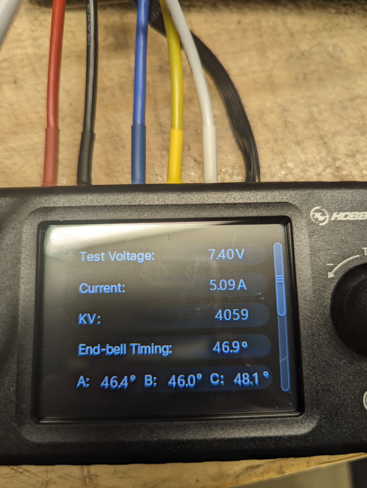
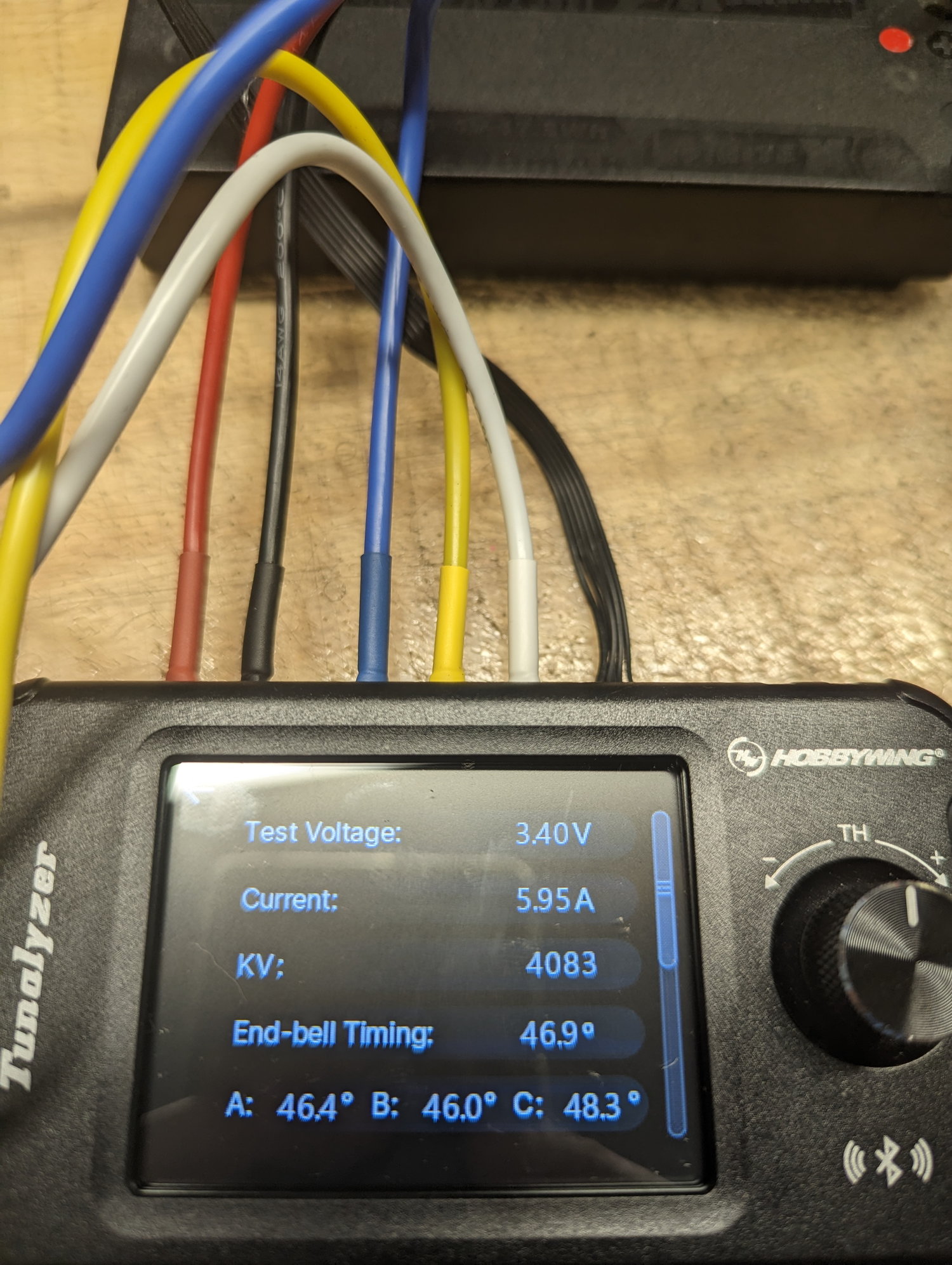
Only difference between these 2 runs is the Tunalyzer test voltage was changed from 7.4 to 3.4. No idea why the current would be higher on the lower voltage. Also, why 3.4? 1S voltage is 3.7.
Only difference between these 2 runs is the Tunalyzer test voltage was changed from 7.4 to 3.4. No idea why the current would be higher on the lower voltage. Also, why 3.4? 1S voltage is 3.7.
05-04-2023 | 06:41 AM
#29
I wasn't sure whether or not they could read the induced voltage from a phase that wasn't being excited.
05-04-2023 | 06:58 AM
#30