


 157Likes
RCHourglass DIY Lap Timing (AKA Cano revised)
 02-04-2022, 11:15 AM
#796
Tech Apprentice
Zround has a nice option for Starting-lights. Building now....First the Arduino code was loaded and it worked. Now working out the power-stage to control DIY lamps.
When ZRound is set at 'Slave', it will only start counting laps after the 'GO' from the Arduino was received. False starts are thus 'punished' by missing the first lap in the counts.
Info for the Arduino-code here: http s://w w w.zround.com/wiki/doku.php/startinglights:kartingocana
I added a random delay (between 0.5 to 2 seconds) in my own code once the last red lamp dims and the green 'GO!" lamp must swith ON. This make a start a bit more chalanging because drivers can't anticipate the geen lamp.
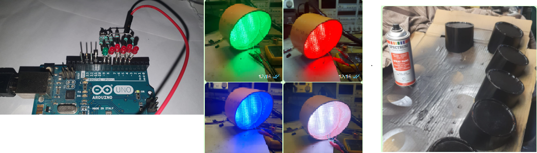
In the picture the LED-strips are tested for colors, alle active gives white. This can be done when a race is not running. During the race it will be green. Red is used when counting down to start. Blue I think is not to be used, but I wire it anyhow to the Arduino.
Lamp housing made from large diameter PVC-pipe, cut one end at 45 dgr. angle. Lamps are LED lightstrips with 120 LED's per meter (RBLS120-03M). The LED-strips are behind a piece of Polycarbonate with structure to spread the light. It was cut in circles from an old ceiling light for 4 fluorescent lamps. Cutting carefully, as it brakes in pieces easy....I used a dremel with a cutting-blade and later trimmed on a belt sander to shape.
When ZRound is set at 'Slave', it will only start counting laps after the 'GO' from the Arduino was received. False starts are thus 'punished' by missing the first lap in the counts.
Info for the Arduino-code here: http s://w w w.zround.com/wiki/doku.php/startinglights:kartingocana
I added a random delay (between 0.5 to 2 seconds) in my own code once the last red lamp dims and the green 'GO!" lamp must swith ON. This make a start a bit more chalanging because drivers can't anticipate the geen lamp.
In the picture the LED-strips are tested for colors, alle active gives white. This can be done when a race is not running. During the race it will be green. Red is used when counting down to start. Blue I think is not to be used, but I wire it anyhow to the Arduino.
Lamp housing made from large diameter PVC-pipe, cut one end at 45 dgr. angle. Lamps are LED lightstrips with 120 LED's per meter (RBLS120-03M). The LED-strips are behind a piece of Polycarbonate with structure to spread the light. It was cut in circles from an old ceiling light for 4 fluorescent lamps. Cutting carefully, as it brakes in pieces easy....I used a dremel with a cutting-blade and later trimmed on a belt sander to shape.
Last edited by PA3EXV; 02-06-2022 at 12:44 AM. Reason: Update
 02-10-2022, 08:17 AM
#797
Tech Apprentice
OK, was quiet for a few days from my end, but work continued on the startinglights.....
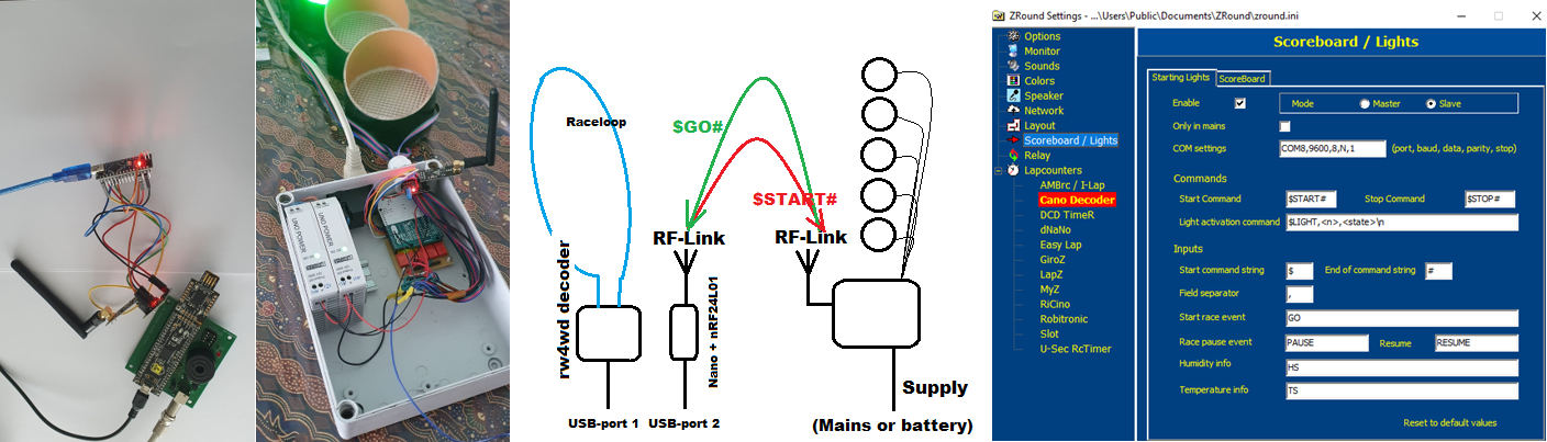
After I was finished the startinglights, and found it working in ZRound (ZRound sends a start countdown command, the lights counts down and once the green lights are lit, ZROUND receives a Go! command back from the startinglights), I discovered a disadvantage: The startinglights need a very long USB_Cable to interface back and forth with ZRound. That can be done in a better way!
I ordered a set of nRF24L01 boards and was able to cut the USB cable and replaced the COM_port communication with an RF-link at 2.4GHz.
So, at the Laptimer-PC is now a Arduino Nano wich has a SPI interfave towards a nRF24L01 module. This transmits the string from ZRound to start the lights towards the 2nd nRF24L01. This will take the received string and informs the Arduino UNO in the startinglight-box to start counting down. After that is complete and the green lamp is ON. that 2nd nRF24L01 module transmits a "$GO#" back to the first and informs ZRound the race can start.
It sound complicated, but now I have the freedom to place my startinglights anywhere I like, no need to have a USB cable to that pole anymore, Furthermore, if the startinglights are equipped with a rechargeable battery, it gives total freedom.
02-10-2022, 09:49 AM
#798
Nice! Wireless + battery might be useful to put the decoder right on the track. But I don't know if Wi-fi or other radio signal might interfer with loop detection.
02-10-2022, 10:10 AM
#799
Tech Apprentice
For the startinglights all the commands over the RFlink were available, including the end-of-message termination character. I have no insight what the communication over serial-COM between PSoC and ZRound is. I am sure someone knows...;-)
02-10-2022, 12:37 PM
#800
In AMB compatibility mode, the protocol was 'reverse engineered' from the source code of some open source timing programs. But with Cano you have all passage information
02-10-2022, 01:00 PM
#801

Zround has a nice option for Starting-lights. Building now....First the Arduino code was loaded and it worked. Now working out the power-stage to control DIY lamps.
When ZRound is set at 'Slave', it will only start counting laps after the 'GO' from the Arduino was received. False starts are thus 'punished' by missing the first lap in the counts.
Info for the Arduino-code here: http s://w w w.zround.com/wiki/doku.php/startinglights:kartingocana
I added a random delay (between 0.5 to 2 seconds) in my own code once the last red lamp dims and the green 'GO!" lamp must swith ON. This make a start a bit more chalanging because drivers can't anticipate the geen lamp.
In the picture the LED-strips are tested for colors, alle active gives white. This can be done when a race is not running. During the race it will be green. Red is used when counting down to start. Blue I think is not to be used, but I wire it anyhow to the Arduino.
Lamp housing made from large diameter PVC-pipe, cut one end at 45 dgr. angle. Lamps are LED lightstrips with 120 LED's per meter (RBLS120-03M). The LED-strips are behind a piece of Polycarbonate with structure to spread the light. It was cut in circles from an old ceiling light for 4 fluorescent lamps. Cutting carefully, as it brakes in pieces easy....I used a dremel with a cutting-blade and later trimmed on a belt sander to shape.
Nice, In the past I did build one too which also automaticly starts the RCM software with a variable pause time from count 3 to the imaginairy zerro.
F1 style starting light.
02-10-2022, 01:34 PM
#802
Tech Apprentice
Great job Roelof! I see that post of you for the first time. Very similar in functionallity. Good one you also included the LED-strip type in your desciption. That might become 'handy' in the future to have more of my cars equipped with lighting. Maybe additional battery for the lights....11V@500mA just for one strip ;-))
Last edited by PA3EXV; 02-10-2022 at 02:02 PM.
02-11-2022, 01:28 AM
#803
Great job Roelof! I see that post of you for the first time. Very similar in functionallity. Good one you also included the LED-strip type in your desciption. That might become 'handy' in the future to have more of my cars equipped with lighting. Maybe additional battery for the lights....11V@500mA just for one strip ;-))
My goal was to use red LED lights so not to use any red filter and no high power. If you look up so called COB LED's you will find high bright LED's but only in several white colors.
02-11-2022, 01:48 AM
#804
Tech Apprentice
This PIC controler can be set in 2 different modes. A fast multiplexing so even when you see 5 lights burning just one is actually on that will keep the power down or you can set non multiplexing for the use of relais to switch bigger lights.
My goal was to use red LED lights so not to use any red filter and no high power. If you look up so called COB LED's you will find high bright LED's but only in several white colors.
My goal was to use red LED lights so not to use any red filter and no high power. If you look up so called COB LED's you will find high bright LED's but only in several white colors.
02-11-2022, 03:39 AM
#805
Tech Initiate
Verry nice work !! Did you try programmable led?
About RCTiming, you can decode the "board" port (TCP) with an arduino "Mega" or "Due" with "Ethernet Shield" to take the countdown and convert it ot Start Lights
i made a similar project few month ago using Rctiming "Board" port
Ludo
About RCTiming, you can decode the "board" port (TCP) with an arduino "Mega" or "Due" with "Ethernet Shield" to take the countdown and convert it ot Start Lights
i made a similar project few month ago using Rctiming "Board" port
Ludo
Last edited by zouky23; 02-11-2022 at 03:50 AM.
02-12-2022, 12:24 PM
#806
Tech Rookie
What type of balun is needed as I can get a voltage or current type?
Regards,
Nick.
02-12-2022, 12:59 PM
#807
Tech Apprentice
 02-12-2022, 03:35 PM
#808
Tech Rookie
We have damaged to our AMB RC black box that sits between the transponder loop and the decoder.
After reading this thread, I purchased a balun, but did not realise that there were different types (current or voltage are examples).
Opening the balun thatI have purchased, it does not look like the one on page 15 inside and now we are worried that we have purchased the wrong type.
I purchased a "High quality balun - 200W 6:1 balun - suit t2fd antenna / doublet"
I have also purchased a "balun" kit but this is going to take weeks to arrive and our black box has been damaged.
I have looked at the schematics for the balun on pages 15 and 16 but it does not tell me which type to purchase "off the shelf".
Regards,
Nick.
Last edited by terminator_2; 02-12-2022 at 03:49 PM.
02-13-2022, 01:17 AM
#809
Tech Apprentice
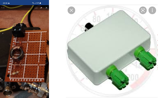
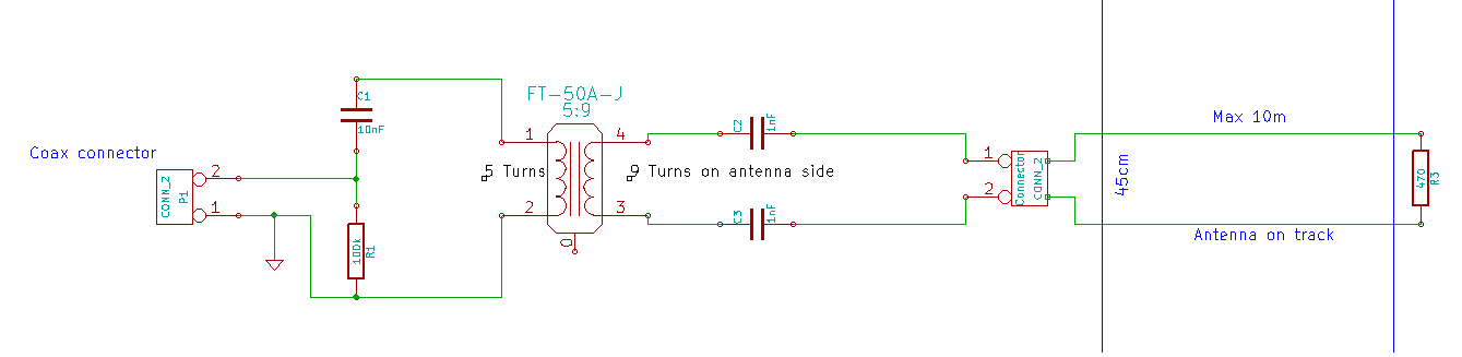
Based on the schematic that shows the solution posted by Condac, it should be fairly simple and cost-effective to build such a box from parts yourself. The Balun you ordered is way too overdone, it is mainly used for transmitters that handle power in the range of 200W. In our case, we need only a small ferrite core of type FT-50A-J, make one winding of 5 turns, and another with 9 turns. Add a few capacitors and a resistor and you're done for less than €2. The plastic box to make it weatherproof is the most expensive part...See the picture how that then looks like.
02-16-2022, 05:22 AM
#810
Tech Rookie
Thanks for info but i (we) are finding it very difficult to source a ferrite core FT-50A-J in the Uk .... if i can find an equivalent, would this be bad? We can only import from America and pay high shipping fees
What Copper wire thickness should i be looking to use or does this not matter either?
Thanks in advance.
Nick.
What Copper wire thickness should i be looking to use or does this not matter either?
Thanks in advance.
Nick.