


 157Likes
RCHourglass DIY Lap Timing (AKA Cano revised)
 11-12-2017, 04:20 PM
#1
What is it?
RC Hourglass is a GITHuB project to develop a DIY automatic timing system that can be used in RC racing and other sporting events. The focus of the project is hardware design of the pieces of the system. The hardware is compatible with existing lap timing software. The project idea comes from two other threads in RCTech forums about lap timing devices design by Howard Cano.
The scope of the project is to simplify the design, document the building process and add new features.
Project status
The project is tested succesfully and actively developed.
Decoder schematic and firmware published.
Transponder schematic published. Firmware and source published.
New features of 0.5 firmware
- Full PIC programming
- Better RC4 Hybrid detection (preamble detector was 0xF916, now it's 0x7916)
- AMBRc compatibility mode (to use with other timing softwares)
- Tranx compatibility mode (for Rentix software compatibility)
- New RCHouglass protocol that extends passage record with hits, quality, voltage and temp information
- Second serial port support.
- Beeper can be configured as a pulse signal (Freq = 0) for beeper that only need an enable signal.
- Commands to set and get decoder time.
- Setup of emulation mode at startup.
New features of 0.6 firmware
- Correction of serial port emulation mode setting
New features of 0.7 firmware
- Correct transponder number decoding causing numbers above 9.999.999.
- AmbRc protocol parsing relaxed for broader compatibility.
Licensing: Howard Cano orignal licensing and some donationware licensing apply. See GITHub page for details.
First part of the project, the decoder, is made of Cano's loop amplifier and input amplifier connected directly to a PSOC development board. The assembly of the decoder that can be easily made on perfboard. Also the use of PSOC allows to have direct power and COM serial port connection through USB.
In the thread a full building report/instruction is shown
For somebody who wants to try the bulding the firmware hex file is available on GitHUB and the project wiki:
https://github.com/mv4wd/RCHourglass
GitHub Wiki
Tools needed are PSOC Creator (PSOC programmer) to flash the HEX image, and Cypress USB Com drivers (registration required to download).
For the transponder build, the PIC can be programmed with the decoder hardware.

RCHourglass transponder
RC Hourglass is a GITHuB project to develop a DIY automatic timing system that can be used in RC racing and other sporting events. The focus of the project is hardware design of the pieces of the system. The hardware is compatible with existing lap timing software. The project idea comes from two other threads in RCTech forums about lap timing devices design by Howard Cano.
The scope of the project is to simplify the design, document the building process and add new features.
Project status
The project is tested succesfully and actively developed.
Decoder schematic and firmware published.
Transponder schematic published. Firmware and source published.
New features of 0.5 firmware
- Full PIC programming
- Better RC4 Hybrid detection (preamble detector was 0xF916, now it's 0x7916)
- AMBRc compatibility mode (to use with other timing softwares)
- Tranx compatibility mode (for Rentix software compatibility)
- New RCHouglass protocol that extends passage record with hits, quality, voltage and temp information
- Second serial port support.
- Beeper can be configured as a pulse signal (Freq = 0) for beeper that only need an enable signal.
- Commands to set and get decoder time.
- Setup of emulation mode at startup.
New features of 0.6 firmware
- Correction of serial port emulation mode setting
New features of 0.7 firmware
- Correct transponder number decoding causing numbers above 9.999.999.
- AmbRc protocol parsing relaxed for broader compatibility.
Licensing: Howard Cano orignal licensing and some donationware licensing apply. See GITHub page for details.
First part of the project, the decoder, is made of Cano's loop amplifier and input amplifier connected directly to a PSOC development board. The assembly of the decoder that can be easily made on perfboard. Also the use of PSOC allows to have direct power and COM serial port connection through USB.
In the thread a full building report/instruction is shown
For somebody who wants to try the bulding the firmware hex file is available on GitHUB and the project wiki:
https://github.com/mv4wd/RCHourglass
GitHub Wiki
Tools needed are PSOC Creator (PSOC programmer) to flash the HEX image, and Cypress USB Com drivers (registration required to download).
For the transponder build, the PIC can be programmed with the decoder hardware.
RCHourglass transponder
Last edited by mv4wd; 05-14-2019 at 05:34 AM. Reason: Update release
 11-12-2017, 04:40 PM
#3
How to use
The decoder uses the same protocol as the original Cano decoder, so any software compatible should work. I've tested it with ZRound. Enable Cano decoder and insert the correct COM port number under decoder configuration.

ZRound setup
As an added feature, transponder ID decoding is done in firmware, so Zround will show a number that matches the number printed on the transponder.
If you connect directly with a terminal software like PUTTY to the serial port, some commands are available
VERSION - will show a version message
LICENSE - will show a licensing message
CANO MODE - uses the Cano protocol with decoded transponder ID (this is the defaul at power on)
CANO CLASSIC MODE - uses the Cano protocol without decoded transponder ID (as the original)
MONITOR MODE - Will output every packet received (debug mode)
Note:no echo is given on terminal, enter return and you should get the response to the command
Compatibility: the decoder has the same compatibility as the original, so AMBRC, Cano transponders MRT and Mylaps RC3 or Hybrid. No RC4 'pure' compatibility.
The decoder uses the same protocol as the original Cano decoder, so any software compatible should work. I've tested it with ZRound. Enable Cano decoder and insert the correct COM port number under decoder configuration.
ZRound setup
As an added feature, transponder ID decoding is done in firmware, so Zround will show a number that matches the number printed on the transponder.
If you connect directly with a terminal software like PUTTY to the serial port, some commands are available
VERSION - will show a version message
LICENSE - will show a licensing message
CANO MODE - uses the Cano protocol with decoded transponder ID (this is the defaul at power on)
CANO CLASSIC MODE - uses the Cano protocol without decoded transponder ID (as the original)
MONITOR MODE - Will output every packet received (debug mode)
Note:no echo is given on terminal, enter return and you should get the response to the command
Compatibility: the decoder has the same compatibility as the original, so AMBRC, Cano transponders MRT and Mylaps RC3 or Hybrid. No RC4 'pure' compatibility.
Last edited by mv4wd; 11-13-2017 at 12:00 AM.
11-12-2017, 04:50 PM
#4
The transponder is in progress. I have variuos designs but I want to test a 'fool' idea before releasing them. On GitHub there's the hex file, not the source. Source WILL be released when the project is stable.
 11-12-2017, 06:13 PM
#7
Not wanting to be mean or anything, but if you guys can figure out how to interpret the RC4 transponder protocol, this would be an excellent way to stick it to MyLaps for making all the AMBrc DP and club/house transponders (and MRTs) obsolete with their new firmware.
11-13-2017, 12:09 AM
#8
See it the other way. Market wil be flooded with transponders worth pennies, so you can buy them if you don't want to build your own. Also if timing software allows, you might think to have two systems working together to retrofit an updated system. I don't have a transponder, so I don't have the idea how to interpret RC4 packets. Monitor mode can help on that. If somebody wants to give a try I'll happily add it to the decoder firmware.
11-13-2017, 12:15 AM
#9

 Cano decoder IS a classic
11-13-2017, 06:56 AM
Cano decoder IS a classic
11-13-2017, 06:56 AM
#10
Tech Initiate
Awesome work you're doing. I have ordered the parts and will test it once I build the decoder later this week.
11-13-2017, 08:20 AM
#11
Thank you to all those that have made this possible
I look forward to the day a MyLaps alternative is available to the general public
I look forward to the day a MyLaps alternative is available to the general public
11-15-2017, 01:28 PM
#12
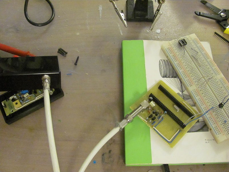
System parts
The lap timing system is made of:
- a tranponder mounted on the veichle
- a loop of wire on the track, connected directly to a loop amplifier
- the decoder module that connects to the loop amplifier trough a shielded antenna wire, and to the PC with USB
- the computer with:
- Cypress virtual COM drivers (google for Cypress USB UART Microsoft certified driver)
- timing software (ZRound or FlipSide)
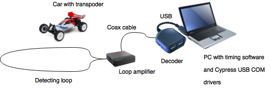
System layout
General building tips:
The project can be built on perfboard. A PCB might be useful, but I think it's better to wait the final design before
investing in a PCB. One of the advantages of the PSOC module is that all the higher frequency logic is within the chip.
Still the circuit amplifies the weak 5MHz transponder signal, so using a breadboard might not be a good idea.
I use to build by bending the components pins and twist/solder them, so only a couple of bridge wires are used.
I don't say that component selection is critical, but when possible I tried to match the paired BJT's HFE and resistors values.
I've used a plastic case with no shielding. Shield can be added later if necessary with aluminum foil, and probably it's most
useful in the loop amplifier where the signal is lower.
For the loop connectors I've used banana style plugs, for the shielded antenna cable I've used sat TV F connectors.
NOTE for the photos. You might notice that BJTs on my decoder board photo are 'swapped'. This is because I used pairs of BC547 and BC307
instead of 2N3904 & 2N3906. In the build instructions I've overlayed a BJT shape to show 2Nxxxx orientation.
The photos of the loop amplifier are for 2N3904 & 2N3906 BJTs.
The lap timing system is made of:
- a tranponder mounted on the veichle
- a loop of wire on the track, connected directly to a loop amplifier
- the decoder module that connects to the loop amplifier trough a shielded antenna wire, and to the PC with USB
- the computer with:
- Cypress virtual COM drivers (google for Cypress USB UART Microsoft certified driver)
- timing software (ZRound or FlipSide)
System layout
General building tips:
The project can be built on perfboard. A PCB might be useful, but I think it's better to wait the final design before
investing in a PCB. One of the advantages of the PSOC module is that all the higher frequency logic is within the chip.
Still the circuit amplifies the weak 5MHz transponder signal, so using a breadboard might not be a good idea.
I use to build by bending the components pins and twist/solder them, so only a couple of bridge wires are used.
I don't say that component selection is critical, but when possible I tried to match the paired BJT's HFE and resistors values.
I've used a plastic case with no shielding. Shield can be added later if necessary with aluminum foil, and probably it's most
useful in the loop amplifier where the signal is lower.
For the loop connectors I've used banana style plugs, for the shielded antenna cable I've used sat TV F connectors.
NOTE for the photos. You might notice that BJTs on my decoder board photo are 'swapped'. This is because I used pairs of BC547 and BC307
instead of 2N3904 & 2N3906. In the build instructions I've overlayed a BJT shape to show 2Nxxxx orientation.
The photos of the loop amplifier are for 2N3904 & 2N3906 BJTs.
Last edited by mv4wd; 11-15-2017 at 01:57 PM.
11-15-2017, 01:40 PM
#13
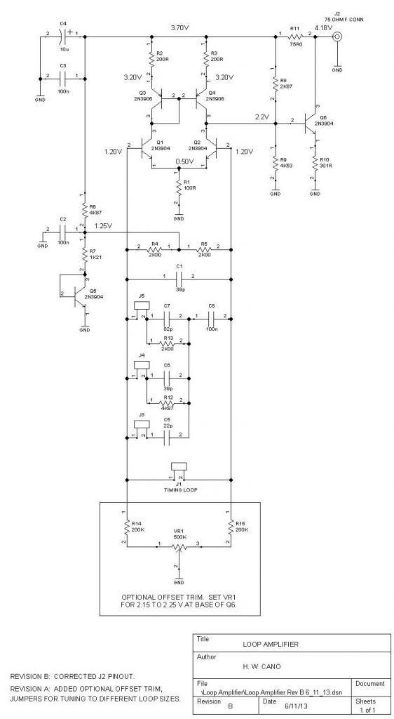
The loop amplifier is the original from the Cano decoder. In my first prototype I skipped the balancing trimmer and resistors and it works. They are included in this build.
Step 1.
Select the components and lay them on the schematic, to check that nothing is missing. Check markings/values twice before soldering.
Notice that J4, C6 and R12 have not been used.
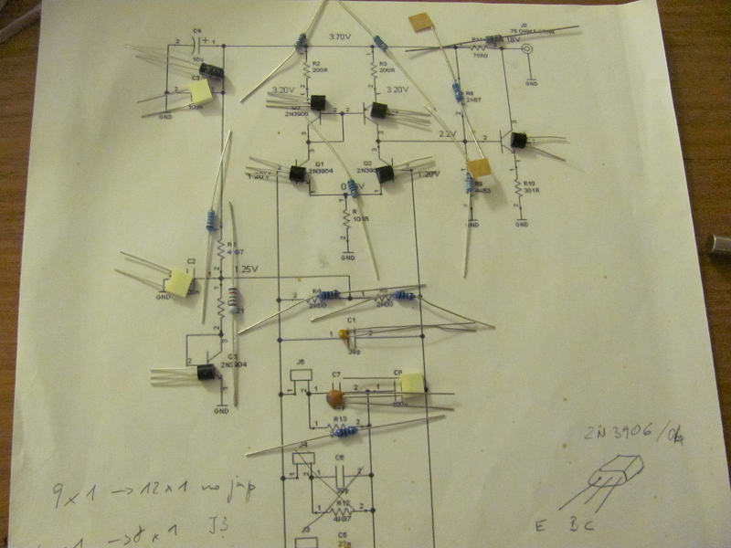
The original schematic
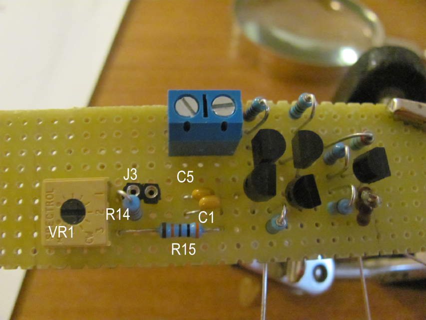
Step 2.
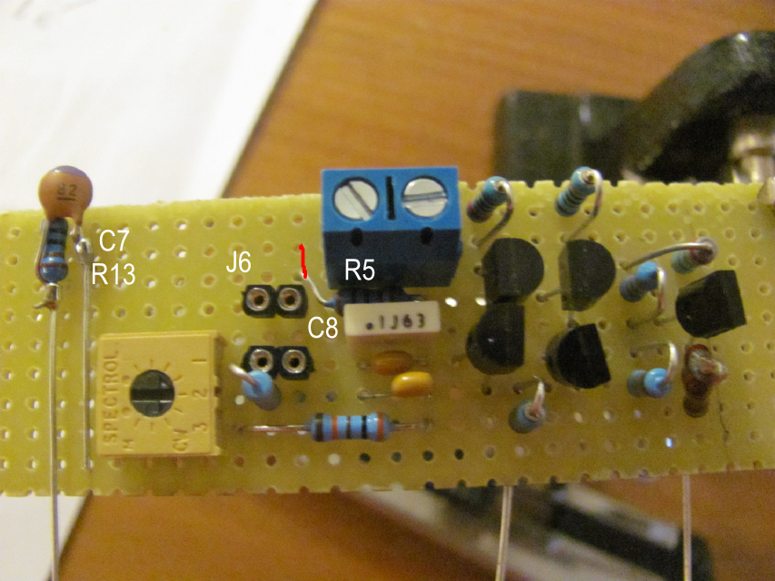
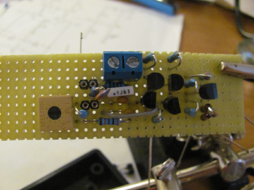
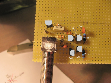
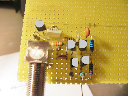
Mount the components. Beware of the connection of R5 (see the red modification) and the connection from C5 to C8.
To make the assebly fit I did join C7 and R13. R10 on my board is a series of two resistors because I didn't have 300 ohm.
The last image shows that ground lines are connect in a 'star' way, so that each component has its own ground path.

Loop amplifier 2

Loop amplifier 3
Loop amplifier 4
Loop amplifier 5
Loop amplifier 6

Loop amplifier 7

Loop amplifier 8
Loop amplifier 9
Testing the loop amplifier
Testing can be done with a digital multimeter set on continuous voltage reading.
The testpoint voltages are in Howard schematic.
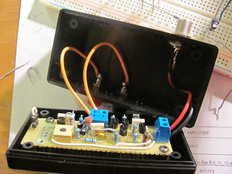
You should power the loop amplifier with 5 volt source (transformer, regulator) through a 75 ohm resistor.
You can use one voltage regulator from the transponder BOM and a battery. Add a 10 uF capacitor on the output of the regulator. Beware of the polarity.
I've tweaked the trimmer so that the measured DC voltage across the two loop inputs (without the loop connected) is zero.
If you're lucky owner of an oscilloscope, you might connect the loop and check the waveform across the 75 ohm resistor when you have a
transponder in the loop.
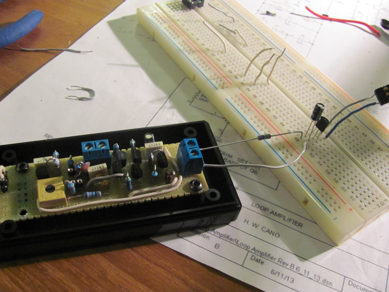
Loop amplifier testing
Do not close the loop amplifier box now!
Step 1.
Select the components and lay them on the schematic, to check that nothing is missing. Check markings/values twice before soldering.
Notice that J4, C6 and R12 have not been used.
The original schematic
Step 2.
Mount the components. Beware of the connection of R5 (see the red modification) and the connection from C5 to C8.
To make the assebly fit I did join C7 and R13. R10 on my board is a series of two resistors because I didn't have 300 ohm.
The last image shows that ground lines are connect in a 'star' way, so that each component has its own ground path.
Loop amplifier 2
Loop amplifier 3
Loop amplifier 4
Loop amplifier 5
Loop amplifier 6
Loop amplifier 7
Loop amplifier 8
Loop amplifier 9
Testing the loop amplifier
Testing can be done with a digital multimeter set on continuous voltage reading.
The testpoint voltages are in Howard schematic.
You should power the loop amplifier with 5 volt source (transformer, regulator) through a 75 ohm resistor.
You can use one voltage regulator from the transponder BOM and a battery. Add a 10 uF capacitor on the output of the regulator. Beware of the polarity.
I've tweaked the trimmer so that the measured DC voltage across the two loop inputs (without the loop connected) is zero.
If you're lucky owner of an oscilloscope, you might connect the loop and check the waveform across the 75 ohm resistor when you have a
transponder in the loop.
Loop amplifier testing
Do not close the loop amplifier box now!
11-15-2017, 01:56 PM
#14
The decoder circuit is the original Phase Detector Amplifier, powered directly with the USB Vdd from the PSOC Module (+5V).
The output of the analog amplifier feeds PSOC input P12_2 and PSOC output P12_3 is used for hysteresis feedback (R11).
Two capacitors and a 5Mhz crystal provide the master clock for the circuit AND timing (Pins 15_0 and 15_1).
The best PPM accuracy crystal should go here.
Step 1.
Select the components and lay them on the schematic, to check that nothing is missing. Check markings/values twice before soldering.
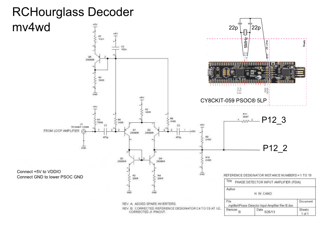
RCHourglass decoder schematic
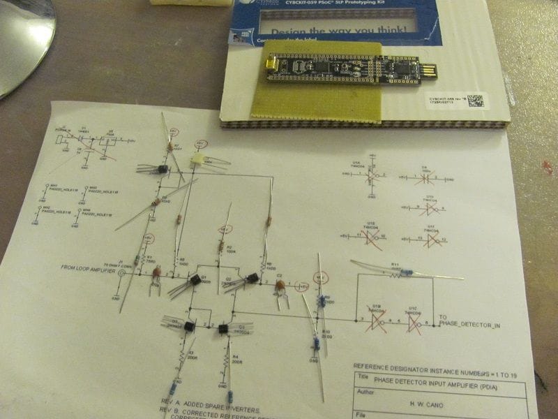
Step 2.
Draw a line where the PSOC connector will go and mark the pins that will be used. With so many of them it's easy to miss by one position,
also some of the silkscreens labels on the PSOC board are offset from the pins. Again check twice.
Mount the input connector and resistor, together with Q5 network. Keep lower R8 and right R7 pins long and unsoldered.
R8 will connect to input connector ground and to circuit ground, R7 pin will be the +5V bus.
The other pins can be cut when soldered.
NOTE for the photos. You might notice that BJTs on my decoder board photo are 'swapped'. This is because I used pairs of BC547 and BC307 instead of 2N3904 & 2N3906. In the build instructions I've overlayed a BJT shape to show 2Nxxxx correct orientation.
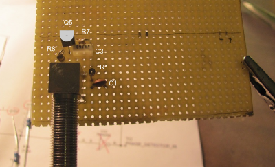
Decoder 2
Mount the other components of the input stage.
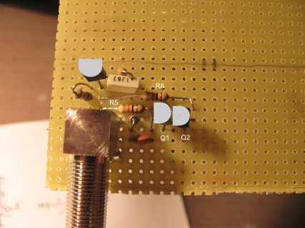
Decoder 3
Decoder 4
Decoder 5
Step 3.
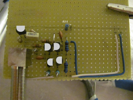
Connect the power rails and the link to the PSOC input and R11
Notice the white GND wire going to the input connector chassis and R8
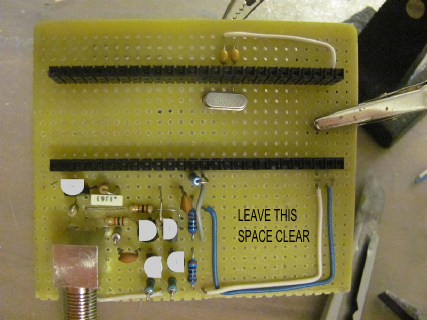
Mount the PSOC connectors. I use the pins on the PSOC board and the strip on the perfboard, but the opposite would be better (never keep exposed pins
that might have voltage and shortcircuit). Double check the spacing between the two connectors. Connect the crystal and capacitors.
Decoder 6
Decoder 7
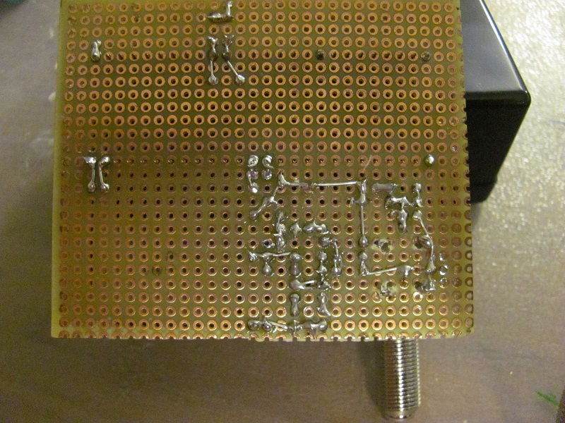
Lower view
Testing the decoder.
Keep the PSOC daughterboard disconnected through testing!
First thing to do would be checking the resistance between the 'to be' PSOC Vcc and GND pins. It should measure around 4K.
If you have the same 5v source used for testing the loop amplifier, connect it to the strip and power all the system (loop amplifier+decoder board).
The loop amplifier should measure the same voltages as when tested alone.
Againg, if you have an oscilloscope, connect the wire to the loop bananas, put a transponder above the loop
and check signal on the pin that will connect to P12_2 of the PSOC.
Final test before PSOC assembly
Programming the firmware
Last thing to do is program the PSOC board. You need the software 'PSOC Programmer'. This can be downloaded from Cypress website
as a stand alone program, or embedded in the full 'PSOC Creator' Suite (many more megabytes to download/install).
If you want to play with PSOCs, download the fulls suite. I think the paltform is worth learning because it REALLY rocks.
Once you've got PSOC Programmer running, connect the PSOC daughterboard from the large USB tab side (no cable needed).
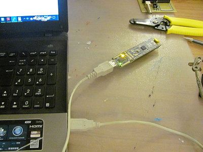
Programming the PSOC
PSOC programmer should detect the kitprog programmer in the board and might prompt you to upgrade the programmer's firmware.
I suggest you do so.
Next click the open file and browse to RCHourglass .hex file (now it's called Version01_BETA.hex).
Click program and you should get a progress bar and a final 'green all ok' sign.
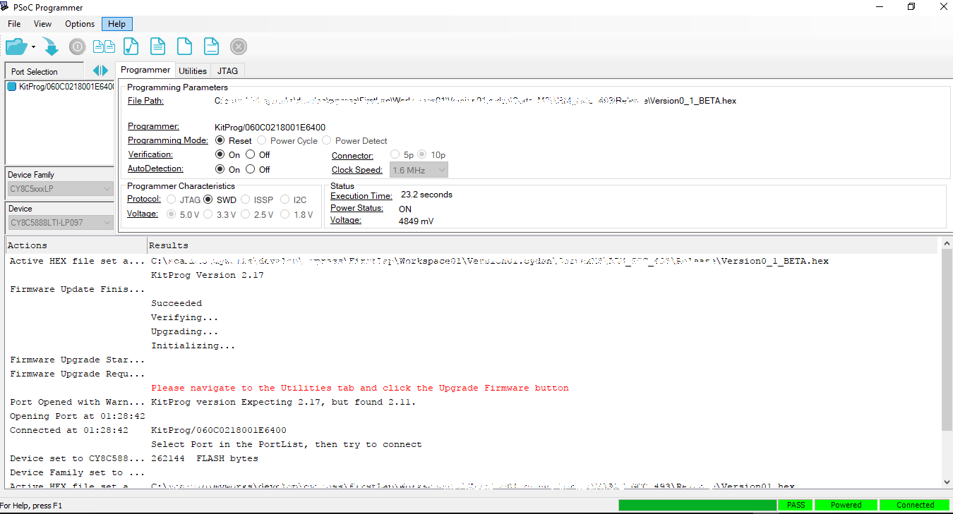
PSOC Programmer software
Install the 'Cypress USB UART Microsoft certified driver' (again downaload from Cypress).
Connect the PSOC to the daughterboard, connect the PSOC from the other port USB (mini USB) with a cable to the PC.
Your system should detect a new hardware, without asking for drivers.
Right click on Computer > Manage, go to the Device management tree, you should find a COM port under Ports (COM & LPT).
Write down the port number but keep in mind that IT MIGHT CHANGE when you connect to other USB ports (or after windows update).
You can now setup ZRound and test a few laps, or test the device standalone with a terminal program (like PUTTY)
To test with PUTTY, open a session to the COM port with parameters speed 115200, 8N1. Issue the VERSION or LICENSE command and you should
get the response from the decoder.
Congratulations, you've made the decoder!
The output of the analog amplifier feeds PSOC input P12_2 and PSOC output P12_3 is used for hysteresis feedback (R11).
Two capacitors and a 5Mhz crystal provide the master clock for the circuit AND timing (Pins 15_0 and 15_1).
The best PPM accuracy crystal should go here.
Step 1.
Select the components and lay them on the schematic, to check that nothing is missing. Check markings/values twice before soldering.
RCHourglass decoder schematic
Step 2.
Draw a line where the PSOC connector will go and mark the pins that will be used. With so many of them it's easy to miss by one position,
also some of the silkscreens labels on the PSOC board are offset from the pins. Again check twice.
Mount the input connector and resistor, together with Q5 network. Keep lower R8 and right R7 pins long and unsoldered.
R8 will connect to input connector ground and to circuit ground, R7 pin will be the +5V bus.
The other pins can be cut when soldered.
NOTE for the photos. You might notice that BJTs on my decoder board photo are 'swapped'. This is because I used pairs of BC547 and BC307 instead of 2N3904 & 2N3906. In the build instructions I've overlayed a BJT shape to show 2Nxxxx correct orientation.
Decoder 2
Mount the other components of the input stage.
Decoder 3
Decoder 4
Decoder 5
Step 3.
Connect the power rails and the link to the PSOC input and R11
Notice the white GND wire going to the input connector chassis and R8
Mount the PSOC connectors. I use the pins on the PSOC board and the strip on the perfboard, but the opposite would be better (never keep exposed pins
that might have voltage and shortcircuit). Double check the spacing between the two connectors. Connect the crystal and capacitors.
Decoder 6
Decoder 7
Lower view
Testing the decoder.
Keep the PSOC daughterboard disconnected through testing!
First thing to do would be checking the resistance between the 'to be' PSOC Vcc and GND pins. It should measure around 4K.
If you have the same 5v source used for testing the loop amplifier, connect it to the strip and power all the system (loop amplifier+decoder board).
The loop amplifier should measure the same voltages as when tested alone.
Againg, if you have an oscilloscope, connect the wire to the loop bananas, put a transponder above the loop
and check signal on the pin that will connect to P12_2 of the PSOC.
Final test before PSOC assembly
Programming the firmware
Last thing to do is program the PSOC board. You need the software 'PSOC Programmer'. This can be downloaded from Cypress website
as a stand alone program, or embedded in the full 'PSOC Creator' Suite (many more megabytes to download/install).
If you want to play with PSOCs, download the fulls suite. I think the paltform is worth learning because it REALLY rocks.
Once you've got PSOC Programmer running, connect the PSOC daughterboard from the large USB tab side (no cable needed).
Programming the PSOC
PSOC programmer should detect the kitprog programmer in the board and might prompt you to upgrade the programmer's firmware.
I suggest you do so.
Next click the open file and browse to RCHourglass .hex file (now it's called Version01_BETA.hex).
Click program and you should get a progress bar and a final 'green all ok' sign.
PSOC Programmer software
Install the 'Cypress USB UART Microsoft certified driver' (again downaload from Cypress).
Connect the PSOC to the daughterboard, connect the PSOC from the other port USB (mini USB) with a cable to the PC.
Your system should detect a new hardware, without asking for drivers.
Right click on Computer > Manage, go to the Device management tree, you should find a COM port under Ports (COM & LPT).
Write down the port number but keep in mind that IT MIGHT CHANGE when you connect to other USB ports (or after windows update).
You can now setup ZRound and test a few laps, or test the device standalone with a terminal program (like PUTTY)
To test with PUTTY, open a session to the COM port with parameters speed 115200, 8N1. Issue the VERSION or LICENSE command and you should
get the response from the decoder.
Congratulations, you've made the decoder!
11-16-2017, 07:17 PM
#15
This is a great project. I am a big fan of Howard's thread, and wanted to build one. I've recently seen lots of really cheap FPGA dev boards, and thought it would be a great way to add flexibility to Howard's design. Looks like this PSOC meets that same criteria. Great find!
One question. Any reason the loop amplifier and phase detector amplifier can't all go on one board?
One question. Any reason the loop amplifier and phase detector amplifier can't all go on one board?