


 157Likes
RCHourglass DIY Lap Timing (AKA Cano revised)
 11-17-2017, 04:26 AM
#16
For the loop amplifier/preamp Howard is the reference for questions. I guess that since the PC might be far from the track, and signal is weak and prone to noise, it's a good idea to amplify it as close as possible to the loop before transmitting the long distance to the PC. Also for high frequencies like this there might be 'reflections' if the impedance is not matched. This would apply if all amplification was at the loop and the input was directly the chip pin. Having phantom power on the loop amplifier is a clever technique used in instrument preamplifiers as well when dealing with low level signals (mic)
 11-17-2017, 04:33 AM
#17

For the loop amplifier/preamp Howard is the reference for questions. I guess that since the PC might be far from the track, and signal is weak and prone to noise, it's a good idea to amplify it as close as possible to the loop before transmitting the long distance to the PC. Also for high frequencies like this there might be 'reflections' if the impedance is not matched. This would apply if all amplification was at the loop and the input was directly the chip pin. Having phantom power on the loop amplifier is a clever technique used in instrument preamplifiers as well when dealing with low level signals (mic)
12-28-2017, 04:24 PM
#18
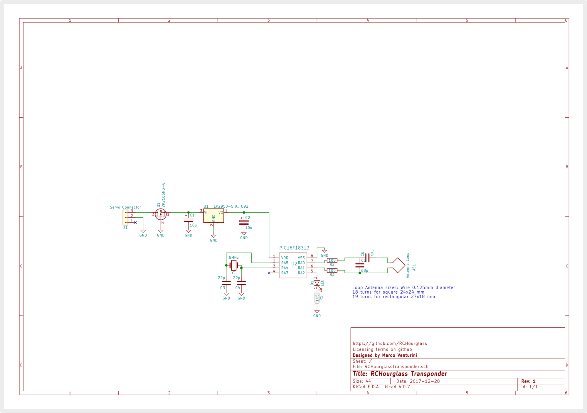
Ok, here's the transponder schematic.
RCHourglass transponder REV A
Like the decoder, it can be build on perfboard and it's very simple.
Soon I'll publish the firmware and the build report for the transponder.
Please make sure you're using the correct PIC16F18313 and not the PIC16LF18313. The L stands for low voltage, so you're gonna fry it in this circuit. This is my first KiCad drawing... and it shows
The antenna driving method is just like Howard's transponder, but all the driving is done inside the PIC. The P Mosfet is a reverse polarity protection and can be omitted if you're sure you're not ever going to mess with your cabling (keep it ). The LED is a low current red led, and the input capacitors C1 and C2 are rated at 16V in my prototype.
RCHourglass transponder REV A
Like the decoder, it can be build on perfboard and it's very simple.
Soon I'll publish the firmware and the build report for the transponder.
Please make sure you're using the correct PIC16F18313 and not the PIC16LF18313. The L stands for low voltage, so you're gonna fry it in this circuit. This is my first KiCad drawing... and it shows
The antenna driving method is just like Howard's transponder, but all the driving is done inside the PIC. The P Mosfet is a reverse polarity protection and can be omitted if you're sure you're not ever going to mess with your cabling (keep it
). The LED is a low current red led, and the input capacitors C1 and C2 are rated at 16V in my prototype.
12-29-2017, 11:00 AM
#19
Tech Apprentice
It is possible to use the low dotage or not, the idea is to run on a 3.5V button battery.
I don't have a battery, or may be add a lipo
I don't have a battery, or may be add a lipo
12-30-2017, 06:59 AM
#20
The standard PIC (no LF) has a min power voltage of 2.5 volt from specs, so it should work. Only output will be lower and/or distorted given the lower voltage swing and drive capability at lower Vdd voltages.
If you skip the voltage regulator it should work
If you skip the voltage regulator it should work
01-06-2018, 12:42 AM
#21
Tech Initiate
I ordered some parts to make me one of the decoder and transponder. What is the transponder coded in CCS C or Microchip C. Do you plan to release the code for the transponder? If so I may try to see if I could get it to report temp and pack voltage.
01-07-2018, 03:35 PM
#22
RCHourglass transponder prototype
The transponder build instructions and firmware are on the GitHub wiki/repository.
The firmware is written in ASM code and it contains Howard's numbers. Also a pre-built firmware hex is available for direct flashing. Please let me know your build results.
The transponder should also be compatible with Mylaps decoders, unless they are patched to the latest firmware.
Last edited by mv4wd; 01-07-2018 at 03:48 PM.
01-07-2018, 03:42 PM
#23
We can go with a similar schema but beware that CANO protocol to the PC does not support voltage/temperature or number of hits report.
This might need implementing a different (or an alternative) protocol to the serial port.
Also I think that temperature of the transponder is quite useless, and since it's nowhere close to the motor temperature which is the important one. Also the voltage, being powered with the bec, is always around 6v regardless of the actual battery voltage. Maybe we should connect directly to the battery, and have a temp probe to mount on the motor. The problem is that right now the pic has just 1 pin free...which is also a 'reduced pin' in capabilities (see the datasheets)
 01-07-2018, 08:25 PM
#24
Tech Initiate
Yes I want pack voltage and motor and/or ESC temps.
01-08-2018, 04:17 AM
#25
For voltage sensing, a resistor ladder to bring input voltage down between 0 and 5v could be connected to the internal ADC. Still I would power the entire transponder from battery rather than crossing wires from before and after the ESC BEC.
The problem is that with the 8 pin chip RA3 (that is free) cannot be used as an analog input for the ADC (unless I'm not understanding the datasheet).
For temperature sensing, a 1 wire temp sensor might be used. We need 1 pin to drive the comunication. Maybe it can work in parallel with the LED or maybe we need to remove the led to get temperature reading ... this should be investigated, but also phisical connection from the transponder to the sensor must be investigated.
01-08-2018, 08:32 PM
#26
Tech Initiate
I got a package of goodies coming from DigiKey Friday.
I want to get the decoder and amp working with the transponder first.
I will see about moving the code to CCS C when I have a working test bed that I know works. I will try and port the code to C and just make it work like the asm code. If I can get the code moved over to C moving to a bigger PIC will be a lot easier. I could maybe then add work on adding the temp and voltage stuff.
01-09-2018, 12:13 AM
#27
Tech Apprentice
May be you can use a PIC16F18323, I think the asm code will be the same and you have 3 ADC more
on RCx pin.
For me, the problem will be to have more transponder number, I need 100 transponder ans maybe more.
We can't change the transponder during the day and their is 40 places on the gate...
on RCx pin.
For me, the problem will be to have more transponder number, I need 100 transponder ans maybe more.
We can't change the transponder during the day and their is 40 places on the gate...
01-09-2018, 12:38 AM
#28
Tech Apprentice
Does you know how to generate transponder number, I have found some program to make it, but it is not on the same format ?
01-09-2018, 04:14 AM
#29
For bigger PIC you mean a higher pin count device? As suggested by mroc, PIC16F18323 works exactly the same as PIC16F18313 but with more pins (14) that allow to have tons of I/O to connect temp or voltage sensor. I think the code should work as well on it. I didn't bother because small form factor is what I prefer on 1/10 model. About porting to C, I think the task can be done. Timing of the modulation bit must be perfect (maybe you can inline asm code) since every four instructions the next bit must be sent. The rest of the code is hardware setup and delay. Notice that also delay values between packets are important. It's reported that RCHourglass transponder firmware works also on Mylaps decoders, whereas original Cano firmware doesn't. Since the packets are the same, probably the delay between packets is the key difference.
01-09-2018, 04:19 AM
#30
>number packet
>number packet
>number packet
>status 1
>number packet
>number packet
>number packet
>status 2
etc
I don't know the status packets content decoding, and it seems to be verified by MyLaps decoder (that's why Howard included them). If you are using only RCHourglass or Cano decoder you can simply send out only your number packet. And it should work