


F1 style starting light.
 07-06-2015, 03:55 AM
#1

A while ago I was asked if I could build a new starting light for our club because the current one is old and showing errors from time to time.
On the search how an F1 starting light acts I came to this:
http://picprojects.org/projects/f1lights/index.htm
Sadly the source code is not published but the costs for a programmed PIC processor or the complete kit are not that high. You can set your own parameters of all timings and the starting signal is random.
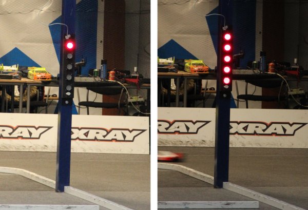
The idea was from a count down based on 10 seconds:
10 to 3: slowly light up all the lights
3 to 0: pause
0 to -3: variable startmoment
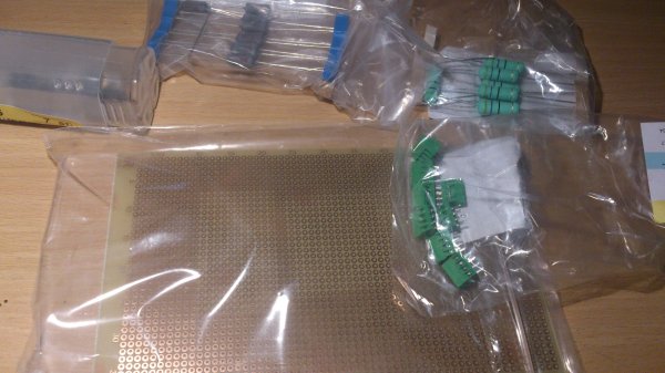
Also the wish was to use LED lights. In the search for affordable high bright red light spots I only cane accross a small LED strip from Kingbright:
https://www.conrad.nl/nl/kingbright-...ma-180382.html
With 2 per light I think it must be bright enough. Also with 10 pieces it was a bit cheaper bud sadly 5 were for a long time in back order.
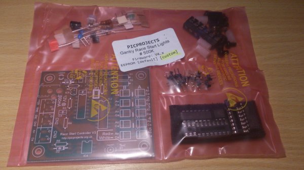
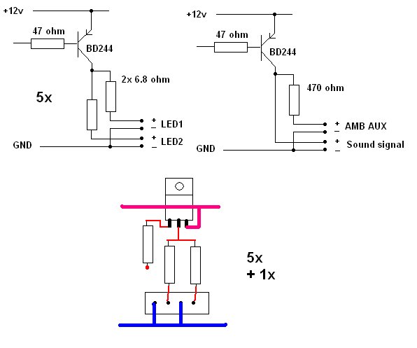
Because the kit can not handle large currents I neded to build a buffer
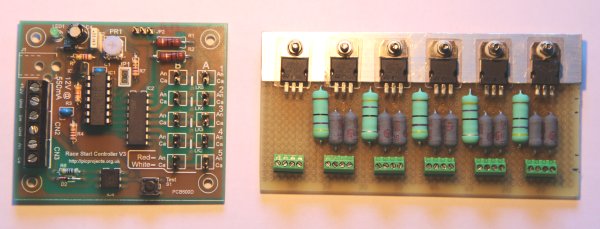
I did setup a small example with 5 to show the club:
Our club was at that time working with an own program which detects the startsignal through the AUX signal on the AMB decoder. Because we also have people using MyRCM which does not support this a different setup was needed, the idea was using a keyboard controler simulating an F5 press (F5 starts the race).
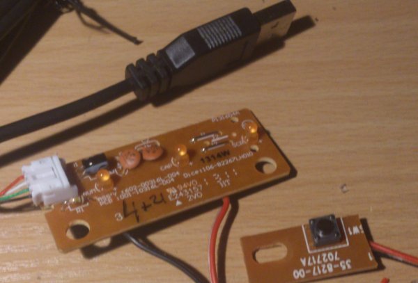
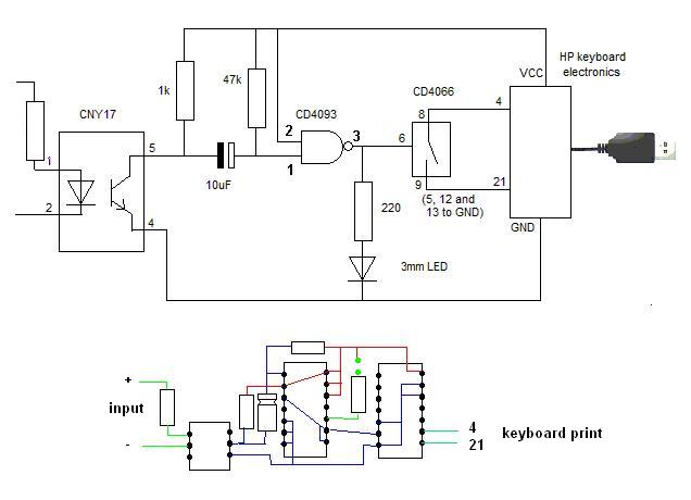
(this transfers the 2 seccond startsignal into a 0.5 sec F5 key press)
It became in handy because a local indoor track also wanted this.
The F5 key press interface:
In a box with start button:
And it works, I can hold the startsignal but only a short key press is simulated:
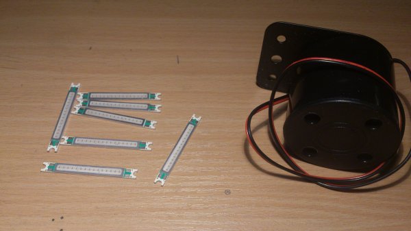
The version for the indoor track, made of some wood, Kingbright LED spot as advised by PICprojects and a small piezo buzzer.
(I also added 2 green bright LED's to make a visual starting signal as well)
Builded at the indoor track:
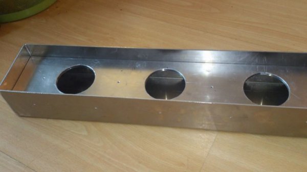
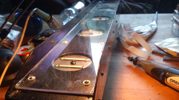
Then after a while I had all parts and materials to finish the one for my club. It will be in all aluminium to have stand everything in the outside weather and flying cars
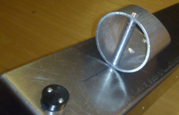
The first hole for the 1st light spot:
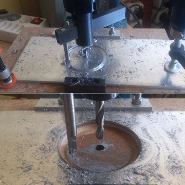
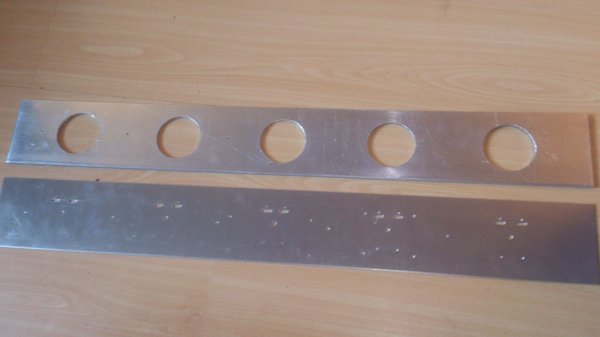
After a lot of drilling:
Under in the case will come the power and data connector:
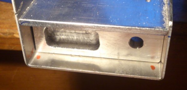
On the back 2 rings will be placed to mount it on a pole.
All electronics on its place, as a power supply I used a 24 watt LED power supply
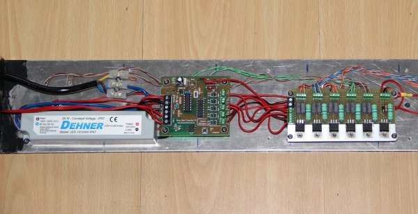
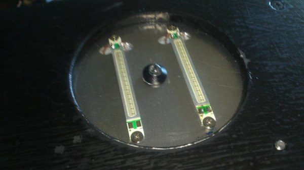
The LED spots are like this. 2 LED strips and in the middle a very high bright 5mm green LED
The working so far:
(with this camera the high brightness is filtered out but it is bright
Thats it so far.
On the search how an F1 starting light acts I came to this:
http://picprojects.org/projects/f1lights/index.htm
Sadly the source code is not published but the costs for a programmed PIC processor or the complete kit are not that high. You can set your own parameters of all timings and the starting signal is random.
The idea was from a count down based on 10 seconds:
10 to 3: slowly light up all the lights
3 to 0: pause
0 to -3: variable startmoment
Also the wish was to use LED lights. In the search for affordable high bright red light spots I only cane accross a small LED strip from Kingbright:
https://www.conrad.nl/nl/kingbright-...ma-180382.html
With 2 per light I think it must be bright enough. Also with 10 pieces it was a bit cheaper bud sadly 5 were for a long time in back order.
Because the kit can not handle large currents I neded to build a buffer
I did setup a small example with 5 to show the club:
| + YouTube Video | |
Our club was at that time working with an own program which detects the startsignal through the AUX signal on the AMB decoder. Because we also have people using MyRCM which does not support this a different setup was needed, the idea was using a keyboard controler simulating an F5 press (F5 starts the race).
(this transfers the 2 seccond startsignal into a 0.5 sec F5 key press)
It became in handy because a local indoor track also wanted this.
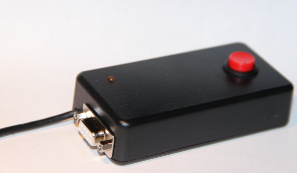
The F5 key press interface:
In a box with start button:
And it works, I can hold the startsignal but only a short key press is simulated:
| + YouTube Video | |
The version for the indoor track, made of some wood, Kingbright LED spot as advised by PICprojects and a small piezo buzzer.
| + YouTube Video | |
(I also added 2 green bright LED's to make a visual starting signal as well)
Builded at the indoor track:
| + YouTube Video | |
Then after a while I had all parts and materials to finish the one for my club. It will be in all aluminium to have stand everything in the outside weather and flying cars
The first hole for the 1st light spot:
After a lot of drilling:
Under in the case will come the power and data connector:
On the back 2 rings will be placed to mount it on a pole.
All electronics on its place, as a power supply I used a 24 watt LED power supply
The LED spots are like this. 2 LED strips and in the middle a very high bright 5mm green LED
The working so far:
| + YouTube Video | |
(with this camera the high brightness is filtered out but it is bright
Thats it so far.

 07-07-2015, 03:43 PM
#4
Thanks. This could be the most time consuming project I have done....
In total there are about 150 drilled holes with about 90 with a M3 thread. I have bought a box of 500 stainless steel screws so it can be screwed together with weather resistant screws. In the front a UV resistant 3mm thick lexan plate will be mounted with a special filling tape to keep water outside. The case is done with Allgrund primer which has a special working on aluminium and over itt a shining black industrial paint, all for a long and solid life.
I just finished a F5 interface. Our club resently switched to RCM which will not work with a startsignal on the AUX port. It is based on an keyboard interface with some electronics to convert the returning start signal ino an F5 press to start the timing.
Yesterday I finished the control connector and a connector for the siren.
Now a 2nd layer of paint and assemble it, next week it hast to be installed for a large race.
If I am right, it will all be PnP on the old system.
07-07-2015, 05:44 PM
#5
Cool project. I raced a few times long ago at a track that had something similar, basically a red-yellow-green US traffic light setup. Was different and challenging to watch the light and then switch focus to the cars as the start was underway. Especially since it was off to the side of the track instead of right along the lane like you appear to have it.
07-08-2015, 11:45 AM
#7
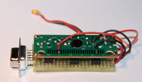
And here the F5 interface for this light:
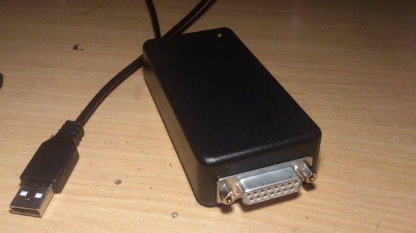
The 15 pole D-sub connector has the same pinout as the AUX port on the AMB decoder so I can use the same connection normally plugged to the AMB decoder now through this device acting as a keyboard pressing F5.
The 15 pole D-sub connector has the same pinout as the AUX port on the AMB decoder so I can use the same connection normally plugged to the AMB decoder now through this device acting as a keyboard pressing F5.
07-17-2015, 03:46 AM
#8
As with all building projects they will come to an end.....
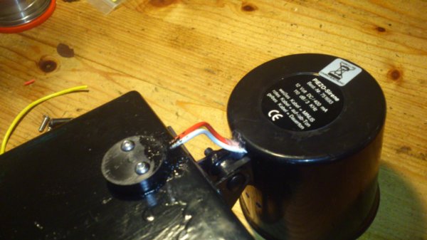
A siren on top of the light as an audio starting signal, it will be faced to the drivers stand for a maximum volume.
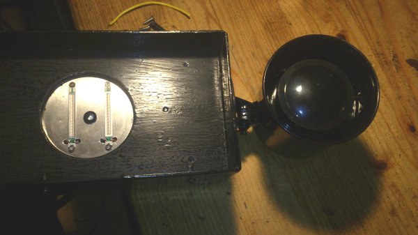
On the rear the cables of the siren are goint into the housing with the help of a plastic piece a made and some kit.
On the side of the front panel a small layer of kit to make it water tight. Then a UV resistance lexan plate in front with also on the side some kit to finish it off.
Then an interface cable was made with the right connector to fit the current connection. A smal pole was put into the ground with some concrete so the light can be mounted on.
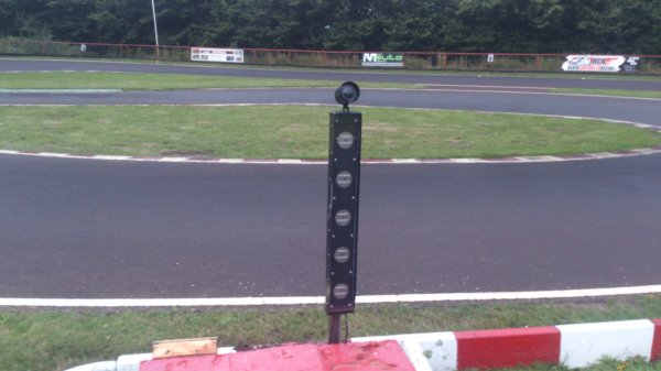
The light was working without any problems, even the F5 key was activateed to start RCM. Also in bright sunlight the LED lights are very visable to see.
Another project made to a succes
A siren on top of the light as an audio starting signal, it will be faced to the drivers stand for a maximum volume.
On the rear the cables of the siren are goint into the housing with the help of a plastic piece a made and some kit.
On the side of the front panel a small layer of kit to make it water tight. Then a UV resistance lexan plate in front with also on the side some kit to finish it off.
Then an interface cable was made with the right connector to fit the current connection. A smal pole was put into the ground with some concrete so the light can be mounted on.
The light was working without any problems, even the F5 key was activateed to start RCM. Also in bright sunlight the LED lights are very visable to see.
Another project made to a succes
07-17-2015, 10:10 AM
#11
Why am I scaring you? It was a nice thing to do with even for me a supprisingly good result but yet the result I wanted. Only the paintjob was something that could be better but these paints do not come in spay cans 
This weekend there is a large race on our track so it will be the 1st time that it will be used. Yesterday evening we did install it and test it, I will not expect any problems.
This weekend there is a large race on our track so it will be the 1st time that it will be used. Yesterday evening we did install it and test it, I will not expect any problems.
 07-17-2015, 11:13 AM
#14
jiml, thanx. There is basically nothing to it, just the right machinery, contacts an the dare to do it.
I have a lathe, a milling machine which is also a drill press, a solder iron and contacts with a metal company who arranged the materials on the right size and the case was allready bended and welded. And electronics is my hobby next to RC racing
If I can get such a "race-stopped" signal from the computer then yes, it can be made possible. It can be done by a small signal on the microprocessor but needs a re-program of the chip of which I have no source code and I am not realy experienced with or otherwise just with a few simple electronic components.
07-19-2015, 12:05 PM
#15
Currently Active Users Viewing This Thread: 1 (0 members and 1 guests)


