


RevTech 17.5 Bad Motor????


 11-17-2011, 06:46 PM
#64
Nothing fancy, but....
http://RapidCompetitionRaceway.webs.com/
Mike Slaughter
11-18-2011, 09:31 AM
#65
okay, i can't just stand by and do nothing .. 
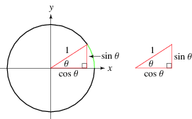
motor design?? it's a simple 9th grade geometry problem. someone please grab a pair of calipers and post the necessary dimensions so we can solve this and move on. (i'll even show my work.)
(hint: correlate the circular diagram below to the endbell when looking at the motor from the back.)
motor design?? it's a simple 9th grade geometry problem. someone please grab a pair of calipers and post the necessary dimensions so we can solve this and move on. (i'll even show my work.)
(hint: correlate the circular diagram below to the endbell when looking at the motor from the back.)
radius of the endbell: .7 inches
distance between the 4 (+) timing marks: .195 inches
The ratio of the hypotenuse of the right triangle to the side opposite the angle we're calcualting is .278571; using a chart that I found here, that value (.278571) closely approximates the sine value for 16 degrees. Since I used 4 timing marks as my reference point, dividing 4 into 16 yields 4 degrees per timing mark. Add 30 degrees to each timing mark to find your total timing.
Unless I'm missing something, I think our "riddle" has been solved.
Last edited by oeoeo327; 11-18-2011 at 11:51 AM.
 11-18-2011, 12:26 PM
#67
I've been running ReVtechs in every class I race since the end of summer. 21.5 blinky, 13.5 boosted, 17.5 boosted and mod (all TC classes or VTA). I've had no issues with any of them. Plenty of speed. Cool temps. I've been using the same boosted 17.5 for around a dozen race days with no problems at all, but I don't generally run my motors at the very brink of meltdown. I run quite a bit of boost, but not quite maxed out. Any more boost, turbo or can timing and it doesn't really seem faster, but definitely generates more heat. Most of the time when I'm trying to find tenths, more boost is the last thing I need.
11-19-2011, 07:59 PM
#68
Tech Initiate
Runnin 17.5 open oval. Just wondering what you guys have found for amp draw? Mine runs strong for the first 2.5 min and then falls off a tenth for the rest of the race. comes off around 140 - 150.
What rotor are you guys using?
Thanks
What rotor are you guys using?
Thanks
11-20-2011, 06:11 AM
#69
Running truck oval in blinky.... Running a pink rotor, runs real good for 4 minutes.
17.5 open- blue rotor, high rpm and running a Tekin, with ~ 70 boost total, try taking some timing out of the motor. 4.10 roll out.
Good luck
17.5 open- blue rotor, high rpm and running a Tekin, with ~ 70 boost total, try taking some timing out of the motor. 4.10 roll out.
Good luck
11-20-2011, 06:54 AM
#70
Tech Initiate
I have the 12.3 and 12.5 high torque and 12.5 broadband rotors plus the stock one. I'm running motor at 30(big line in the middle). I have tried everything from 40 to 50 boost. Runline is 85ft bullring. Rollout out from 3.18 to 3.40. Am I overgeared?
Thanks
Thanks
12-11-2011, 01:35 PM
#71
I am not sure how active this thread is, but I thought it might be a good idea to get this out to the masses and maybe even the manufacturer.
I recently aquired a Revtech 17.5 for usage in my touring car and also share time in my 1/12th pan car, both in blinky(non boosted) classes. Since many of the racers who I interact with use this motor (and wax my tail) and are speed wise very fast, I was very excited with anticipation of running the motor and maybe closing the gap between myself and them. (you know where this story is going,,,,,,,,,,,,,,,,right?????). Well, I soldered in the motor for it's maiden voyage in my 1/12th car and in disbelief found the car motor barely operated when the car was held up, and either only stuttered on the carpet surface or would not move at all. I am not a newbie to installing electronics in cars, and I am very methodical and cautious when installing electronics, this stuff costs too much to be sloppy.
As luck would have it, one of the local "hot shoes" was Trinity sponsored so I figured he could send me in the right direction and get my problem resolved. Well, yes and no His assessment was that the problem was either a bad sensor wire or sensor board within the motor. I had already swapped out the wire (even though, the wire had worked on the motor I had just pulled out 10 minuted earlier). So I parked the motor for that weekend. Following weekend I went to our local "meca of RC= Horsham raceway". I figured I would discuss the problem with others there. The help there was fantastic, no less than 10 racers there looked at the motor and gave their opinions and suggestions and we finally figured it out, here was our findings.
1, on the "B" connection where the stator wires are soldered, the solder
appeared to be too high, possibly contacting the adjustment ring on the
backside of the motor, partially shorting the "B" to the can. I carefully
filed down the connection with the motor inverted so the filings would
not fall into the motor.
2, there is very little clearance between the A,B,C terminals to the can
housing. I cut several sections of electrical tape to insulate the
terminals from the can.
One of the ways it was determined the speedo was not recognizing the sensor was thru the LED's on the Tekin speedo. After doing the above, no problems. Hope this info will be helpful to at least one of my fellow racers.
I recently aquired a Revtech 17.5 for usage in my touring car and also share time in my 1/12th pan car, both in blinky(non boosted) classes. Since many of the racers who I interact with use this motor (and wax my tail) and are speed wise very fast, I was very excited with anticipation of running the motor and maybe closing the gap between myself and them. (you know where this story is going,,,,,,,,,,,,,,,,right?????). Well, I soldered in the motor for it's maiden voyage in my 1/12th car and in disbelief found the car motor barely operated when the car was held up, and either only stuttered on the carpet surface or would not move at all. I am not a newbie to installing electronics in cars, and I am very methodical and cautious when installing electronics, this stuff costs too much to be sloppy.
As luck would have it, one of the local "hot shoes" was Trinity sponsored so I figured he could send me in the right direction and get my problem resolved. Well, yes and no
His assessment was that the problem was either a bad sensor wire or sensor board within the motor. I had already swapped out the wire (even though, the wire had worked on the motor I had just pulled out 10 minuted earlier). So I parked the motor for that weekend. Following weekend I went to our local "meca of RC= Horsham raceway". I figured I would discuss the problem with others there. The help there was fantastic, no less than 10 racers there looked at the motor and gave their opinions and suggestions and we finally figured it out, here was our findings.1, on the "B" connection where the stator wires are soldered, the solder
appeared to be too high, possibly contacting the adjustment ring on the
backside of the motor, partially shorting the "B" to the can. I carefully
filed down the connection with the motor inverted so the filings would
not fall into the motor.
2, there is very little clearance between the A,B,C terminals to the can
housing. I cut several sections of electrical tape to insulate the
terminals from the can.
One of the ways it was determined the speedo was not recognizing the sensor was thru the LED's on the Tekin speedo. After doing the above, no problems. Hope this info will be helpful to at least one of my fellow racers.
 12-11-2011, 02:34 PM
#73
I am not sure how active this thread is, but I thought it might be a good idea to get this out to the masses and maybe even the manufacturer.
I recently aquired a Revtech 17.5 for usage in my touring car and also share time in my 1/12th pan car, both in blinky(non boosted) classes. Since many of the racers who I interact with use this motor (and wax my tail) and are speed wise very fast, I was very excited with anticipation of running the motor and maybe closing the gap between myself and them. (you know where this story is going,,,,,,,,,,,,,,,,right?????). Well, I soldered in the motor for it's maiden voyage in my 1/12th car and in disbelief found the car motor barely operated when the car was held up, and either only stuttered on the carpet surface or would not move at all. I am not a newbie to installing electronics in cars, and I am very methodical and cautious when installing electronics, this stuff costs too much to be sloppy.
As luck would have it, one of the local "hot shoes" was Trinity sponsored so I figured he could send me in the right direction and get my problem resolved. Well, yes and no His assessment was that the problem was either a bad sensor wire or sensor board within the motor. I had already swapped out the wire (even though, the wire had worked on the motor I had just pulled out 10 minuted earlier). So I parked the motor for that weekend. Following weekend I went to our local "meca of RC= Horsham raceway". I figured I would discuss the problem with others there. The help there was fantastic, no less than 10 racers there looked at the motor and gave their opinions and suggestions and we finally figured it out, here was our findings.
1, on the "B" connection where the stator wires are soldered, the solder
appeared to be too high, possibly contacting the adjustment ring on the
backside of the motor, partially shorting the "B" to the can. I carefully
filed down the connection with the motor inverted so the filings would
not fall into the motor.
2, there is very little clearance between the A,B,C terminals to the can
housing. I cut several sections of electrical tape to insulate the
terminals from the can.
One of the ways it was determined the speedo was not recognizing the sensor was thru the LED's on the Tekin speedo. After doing the above, no problems. Hope this info will be helpful to at least one of my fellow racers.
I recently aquired a Revtech 17.5 for usage in my touring car and also share time in my 1/12th pan car, both in blinky(non boosted) classes. Since many of the racers who I interact with use this motor (and wax my tail) and are speed wise very fast, I was very excited with anticipation of running the motor and maybe closing the gap between myself and them. (you know where this story is going,,,,,,,,,,,,,,,,right?????). Well, I soldered in the motor for it's maiden voyage in my 1/12th car and in disbelief found the car motor barely operated when the car was held up, and either only stuttered on the carpet surface or would not move at all. I am not a newbie to installing electronics in cars, and I am very methodical and cautious when installing electronics, this stuff costs too much to be sloppy.
As luck would have it, one of the local "hot shoes" was Trinity sponsored so I figured he could send me in the right direction and get my problem resolved. Well, yes and no
His assessment was that the problem was either a bad sensor wire or sensor board within the motor. I had already swapped out the wire (even though, the wire had worked on the motor I had just pulled out 10 minuted earlier). So I parked the motor for that weekend. Following weekend I went to our local "meca of RC= Horsham raceway". I figured I would discuss the problem with others there. The help there was fantastic, no less than 10 racers there looked at the motor and gave their opinions and suggestions and we finally figured it out, here was our findings.1, on the "B" connection where the stator wires are soldered, the solder
appeared to be too high, possibly contacting the adjustment ring on the
backside of the motor, partially shorting the "B" to the can. I carefully
filed down the connection with the motor inverted so the filings would
not fall into the motor.
2, there is very little clearance between the A,B,C terminals to the can
housing. I cut several sections of electrical tape to insulate the
terminals from the can.
One of the ways it was determined the speedo was not recognizing the sensor was thru the LED's on the Tekin speedo. After doing the above, no problems. Hope this info will be helpful to at least one of my fellow racers.
12-11-2011, 02:43 PM
#74
I think I have our answer:
radius of the endbell: .7 inches
distance between the 4 (+) timing marks: .195 inches
The ratio of the hypotenuse of the right triangle to the side opposite the angle we're calcualting is .278571; using a chart that I found here, that value (.278571) closely approximates the sine value for 16 degrees. Since I used 4 timing marks as my reference point, dividing 4 into 16 yields 4 degrees per timing mark. Add 30 degrees to each timing mark to find your total timing.
Unless I'm missing something, I think our "riddle" has been solved.
It's trig aka college math 112, Sine of theta will give you a workable answer but since your actually measuring from two points on the circumference the sine function is not actually accurate. When I finish calc 2 next term i will give you the right answer or if I come up with it sooner lol. Right now your finding the angle from the origin to cos Theta, which is not on the outer diameter like what your actually trying to find.
12-11-2011, 04:53 PM
#75
Tech Master
iTrader: (13)
It's trig aka college math 112, Sine of theta will give you a workable answer but since your actually measuring from two points on the circumference the sine function is not actually accurate. When I finish calc 2 next term i will give you the right answer or if I come up with it sooner lol. Right now your finding the angle from the origin to cos Theta, which is not on the outer diameter like what your actually trying to find.
If we are measuring from one point to another on the actual circumference(ie: the guy laid a piece of string down from 0 to the 4th hash mark and then measured the length of the string), what we have is an arc length.
Length of arc = (theta/360deg)*2pi*radius
We have the radius(.7in)... And we have the arc length(.195in). Plug those #s in and you get the angle(theta) that corresponds to 4 timing marks. Divide by 4 and you have degrees per hash mark.
My TI-89 is out of batteries or Id do it myself...