


 383Likes
My new Touring.
 04-20-2020, 07:51 AM
#31

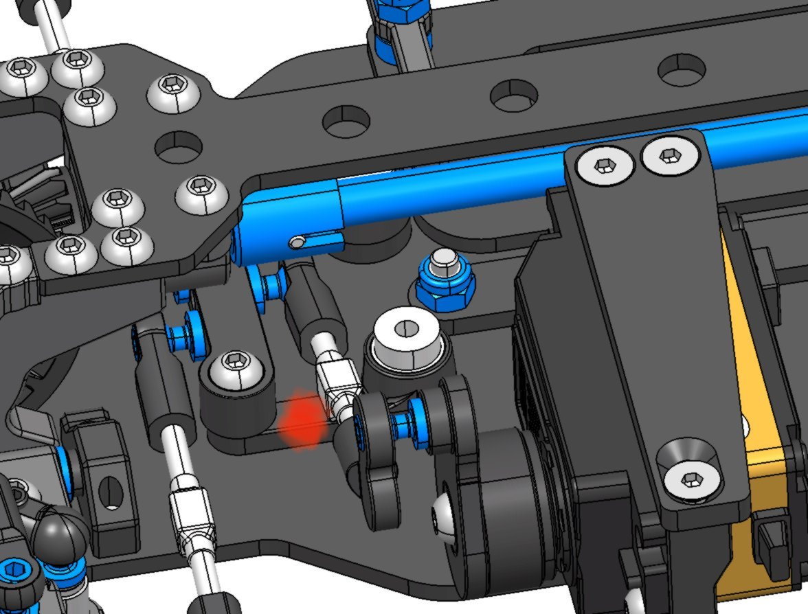
I’m not sure you caught what I was saying. I was referring to the bell crank arm as marked the picture. Why can it not be attached in this location?
or... rotate the servo 90 degrees with the servo saver to the outside, pushing the servo as close as you can to the center, and use a “L” arm for the bell crank.
or... rotate the servo 90 degrees with the servo saver to the outside, pushing the servo as close as you can to the center, and use a “L” arm for the bell crank.
 04-20-2020, 09:22 AM
#32
Placing the link to the place you marked with the red point won't work. When you turn the car to the right, will be fine, but turning to the left, the bridge will hit the ball stud and block the steering.
Last edited by Eotz; 04-20-2020 at 10:48 AM.
04-20-2020, 10:50 AM
#33
In that exact location yes, but the center of the arm is covered by the steering linkage in the pic. If the ball stud were centered on the bell crank arm, I’m sure you could still get more than adequate clearance. And if was raised.
The point I was getting at, is why is the default, the center of the bridge for the ballstud position? has any attempt, by anyone been made to alter this once servos and materials became much stronger than 20 years ago?
The point I was getting at, is why is the default, the center of the bridge for the ballstud position? has any attempt, by anyone been made to alter this once servos and materials became much stronger than 20 years ago?
04-20-2020, 08:21 PM
#34
Tech Master
Not to be a pain but the biggest problem I had with linear steer was gaps and wear in the track. 3 bearings with one on an eccentric allowed compensation for wear. Its very sensitive to too little gap as well. You would feel the bearings slightly bind if you tighten the eccentric too much. either way you know what you are doing but I’d hate to see you have to make revisions later because you missed something that seems trivial.
04-22-2020, 04:39 AM
#35
At the moment nothing is decided. My plan is to made one prototype of each kind of direction and try then.
04-24-2020, 07:33 AM
#36
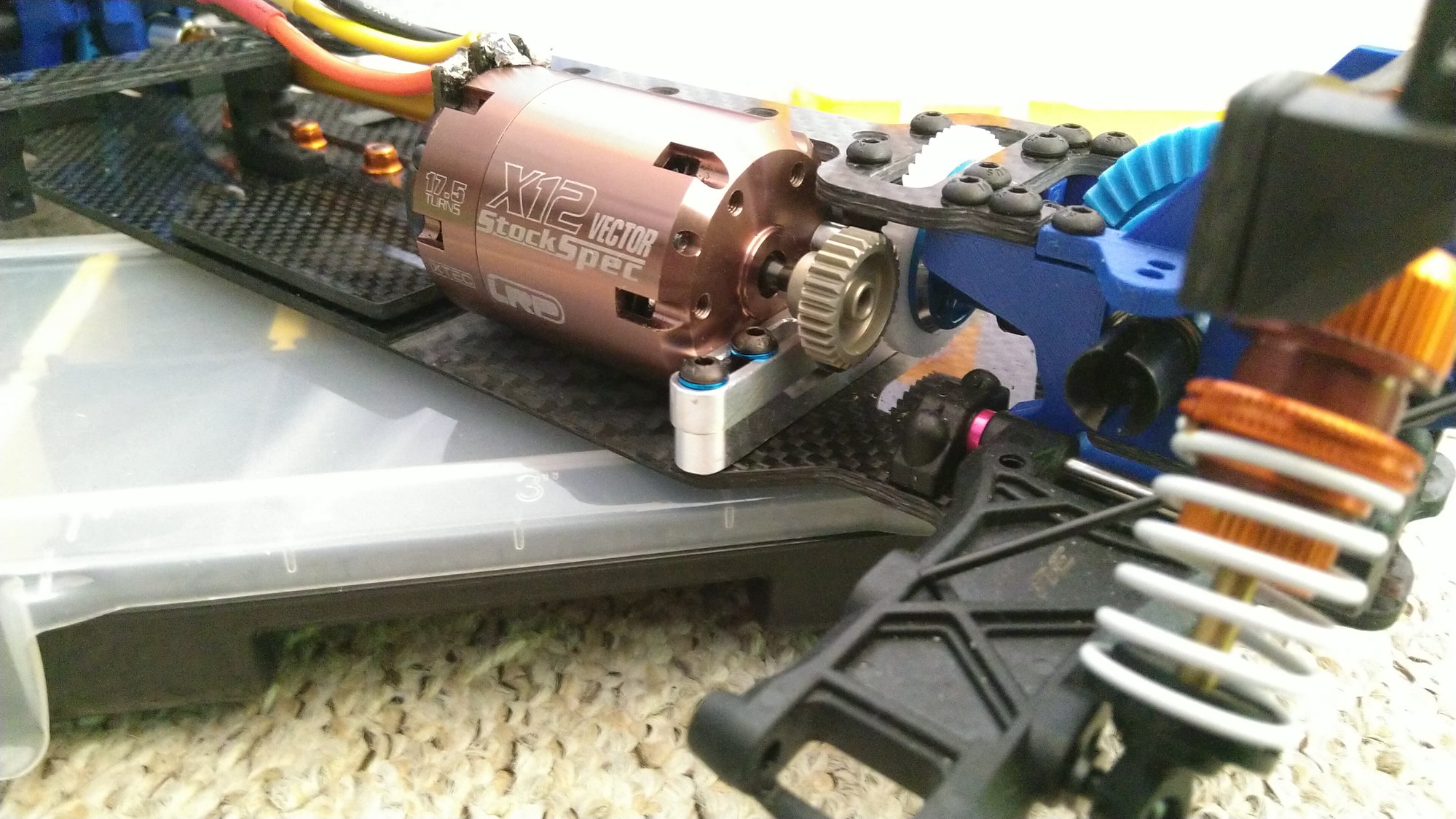
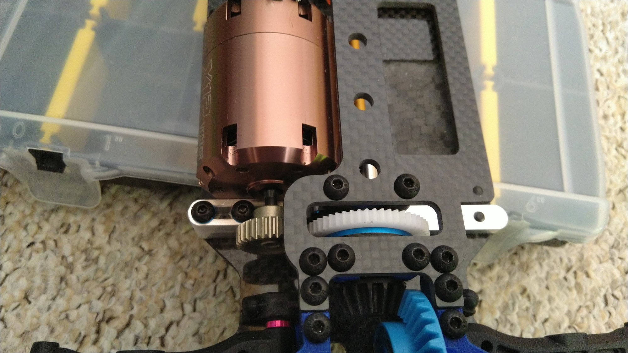
The motor mounts are not 100% finish, but almost. 
04-24-2020, 08:16 AM
#37
So cool 

04-25-2020, 09:54 PM
#38
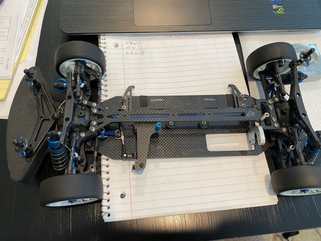
Finished
04-25-2020, 11:29 PM
#39
I like you bulkhead design. To make the motor mount more slim
04-27-2020, 08:58 AM
#40
Tech Rookie
Cool information
05-04-2020, 11:11 AM
#41
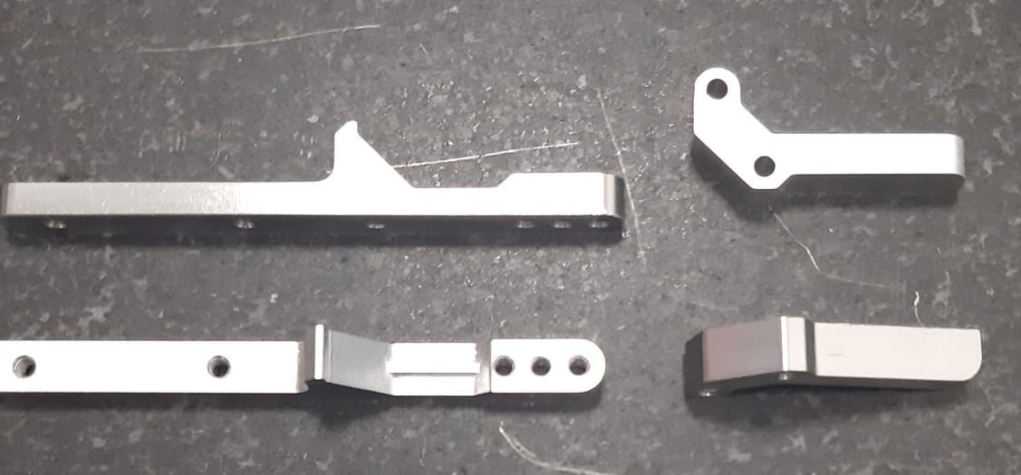
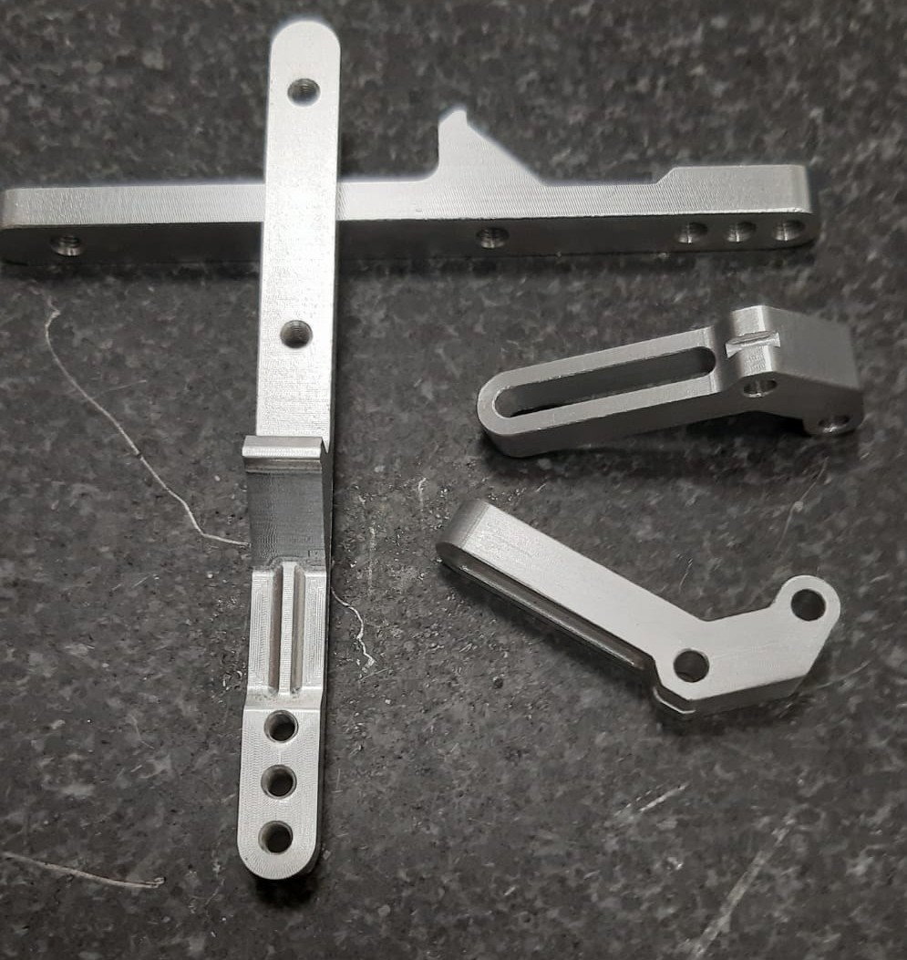
After flying 2000km from Mecanizados Leniz, at the Basque Country, the parts arrived today. Machined in Aluminum 7075. All fitted as expected. Great job.
The project is going slowly (Comparing to wtcc ones) but without pause.
The project is going slowly (Comparing to wtcc ones) but without pause.
10-18-2020, 01:38 PM
#43
Tech Rookie
Yo,I would love to see this car in move
10-21-2020, 03:28 PM
#44
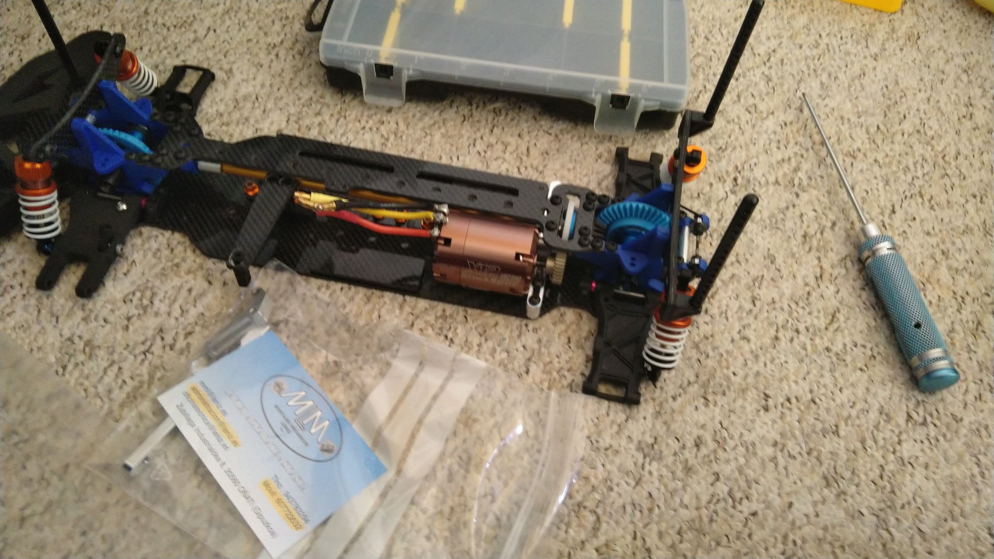
Here is the steering I opted to use on my shaft drive project. It provides full motion without interference. It also incorporates a servo saver in the center linkage post. I’m not sure if it was made by Associated or not but you could easily model it up for your project. I did this one prototype plus 6 more conversions
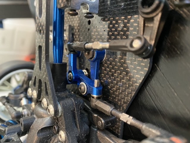
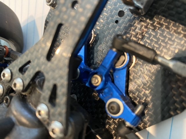
several years ago and still get compliments on its performance.
several years ago and still get compliments on its performance.
10-23-2020, 08:04 AM
#45
Here is the steering I opted to use on my shaft drive project. It provides full motion without interference. It also incorporates a servo saver in the center linkage post. I’m not sure if it was made by Associated or not but you could easily model it up for your project. I did this one prototype plus 6 more conversions
several years ago and still get compliments on its performance.
several years ago and still get compliments on its performance.
This steering looks great. Could you made a 3D model yourself?
Last months I have all in pause, I have no free time and the guy who print the parts for me became father and now, he also have no more time
