


 383Likes
My new Touring.
 04-15-2020, 10:20 AM
#16

I’m interested to see your steering bell crank solution. the Exo Mount is that high so you can get the linkage from the servo to the bell crank. Any lower and it would hit the shaft. Looking at your picture of your completed prototype chassis, I don’t see how you are going to get the linkage to fit.
Unless it causes some sort of weird Ackerman, wouldn’t reversed bellcranks, or a slide rack provide a more compact solution? I know on my TB05 w/full Exo conversion, the linkage from the servo gets trapped between the bridge and the bearing housing of the bell cranks. This is what limits my steering throw, not the knuckles
Unless it causes some sort of weird Ackerman, wouldn’t reversed bellcranks, or a slide rack provide a more compact solution? I know on my TB05 w/full Exo conversion, the linkage from the servo gets trapped between the bridge and the bearing housing of the bell cranks. This is what limits my steering throw, not the knuckles
 04-15-2020, 02:58 PM
#17
pretty sure that the advantage of having the battery weight hanging in the center is annihilated by the fact that the center of mass is a lot higher...
04-15-2020, 10:30 PM
#18
I’m interested to see your steering bell crank solution. the Exo Mount is that high so you can get the linkage from the servo to the bell crank. Any lower and it would hit the shaft. Looking at your picture of your completed prototype chassis, I don’t see how you are going to get the linkage to fit.
Unless it causes some sort of weird Ackerman, wouldn’t reversed bellcranks, or a slide rack provide a more compact solution? I know on my TB05 w/full Exo conversion, the linkage from the servo gets trapped between the bridge and the bearing housing of the bell cranks. This is what limits my steering throw, not the knuckles
Unless it causes some sort of weird Ackerman, wouldn’t reversed bellcranks, or a slide rack provide a more compact solution? I know on my TB05 w/full Exo conversion, the linkage from the servo gets trapped between the bridge and the bearing housing of the bell cranks. This is what limits my steering throw, not the knuckles
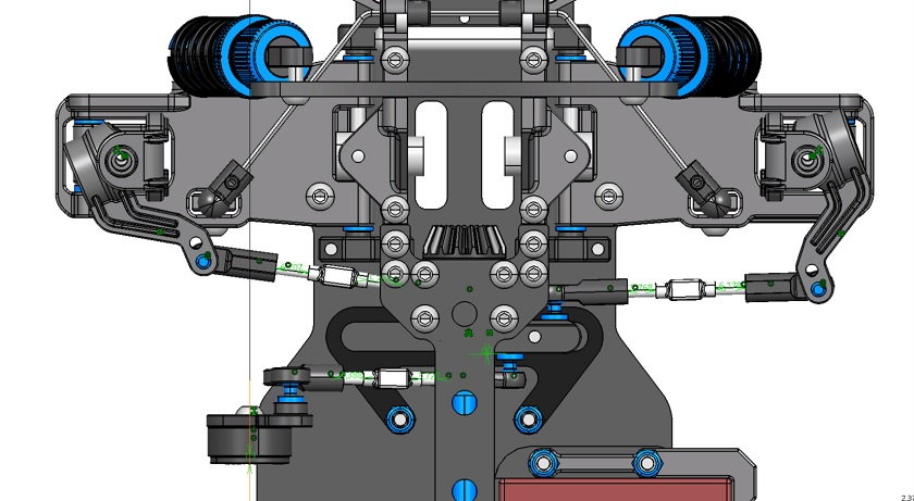
The kinematics works well. But the spaces are minimal. I will have to fine-tune the trasmitter's dual rate.
Last edited by Eotz; 04-15-2020 at 10:59 PM.
04-15-2020, 10:38 PM
#19
Last edited by Eotz; 04-16-2020 at 04:29 AM.
04-17-2020, 05:09 AM
#20
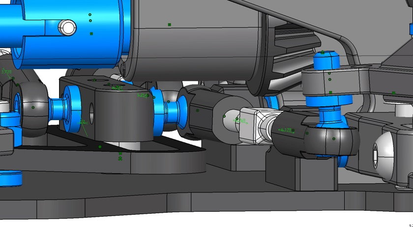
The original car and the Exo have similar steering setups. Running the Xray suspension and out hubs on mine, I get 5 degrees less throw per side than my Xray. As you can see in the pics, the lower ball cup hits the bell ranks at full throw in both directions.
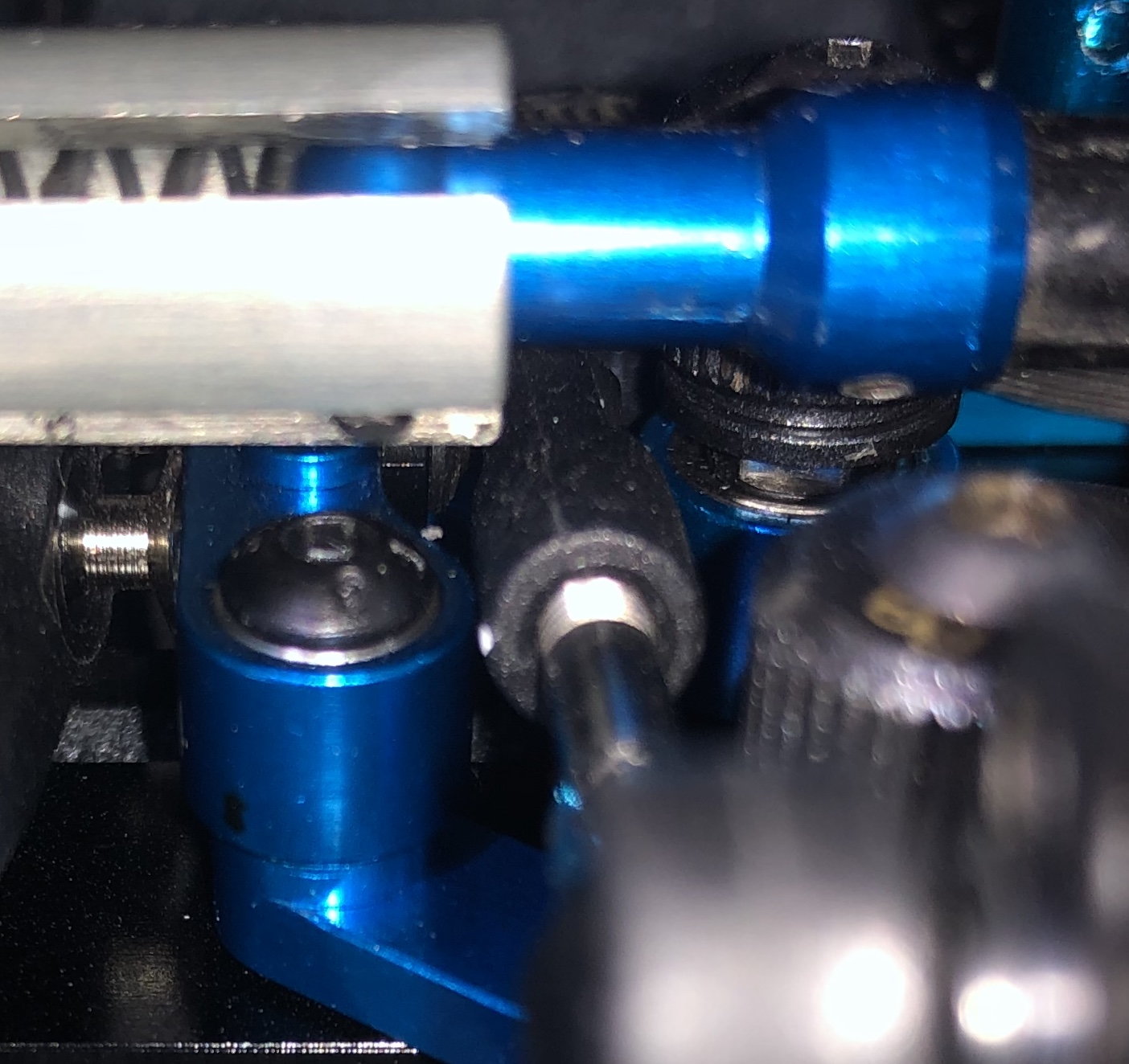
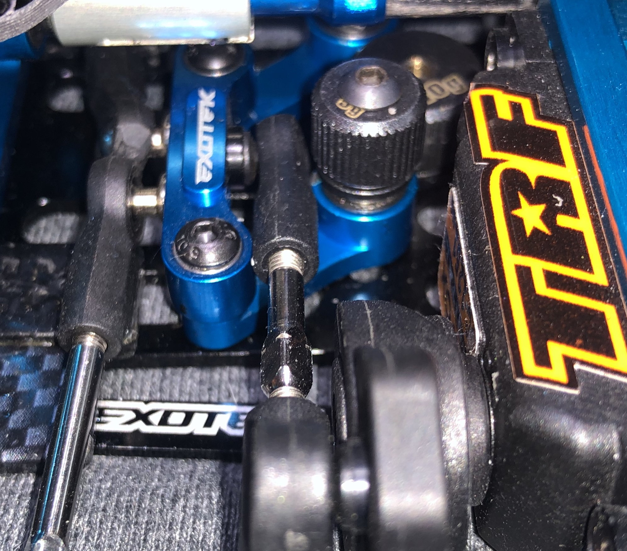
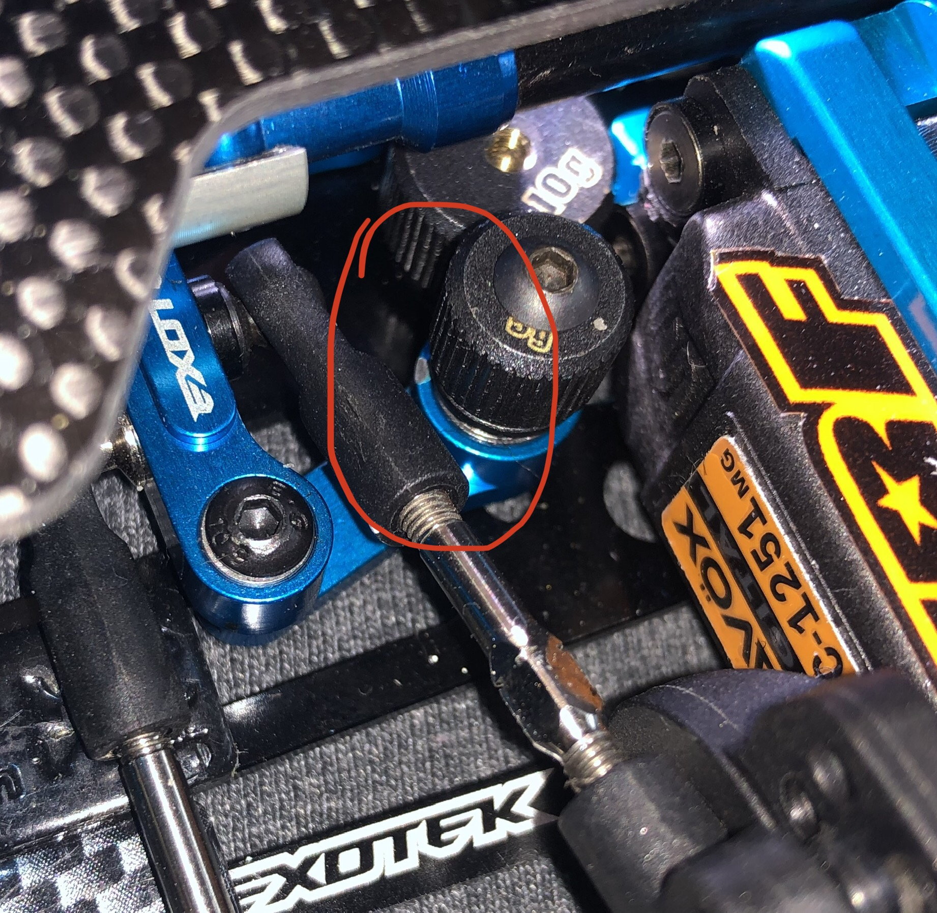
You can see where it has caused some damage to the parts from being at max throw.
You can see where it has caused some damage to the parts from being at max throw.
04-17-2020, 05:43 AM
#21
Looks really narrow.
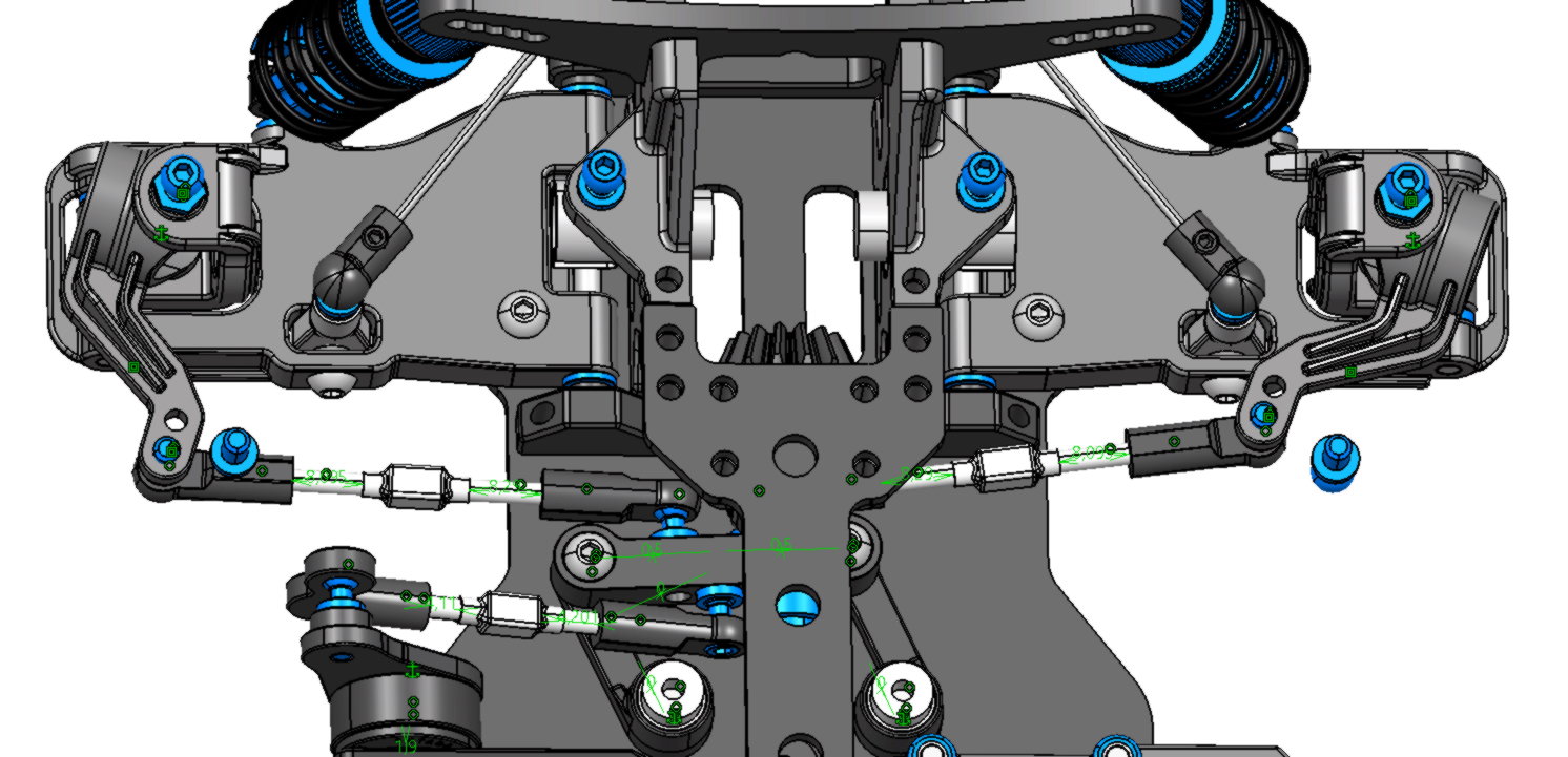
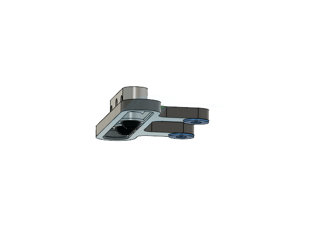
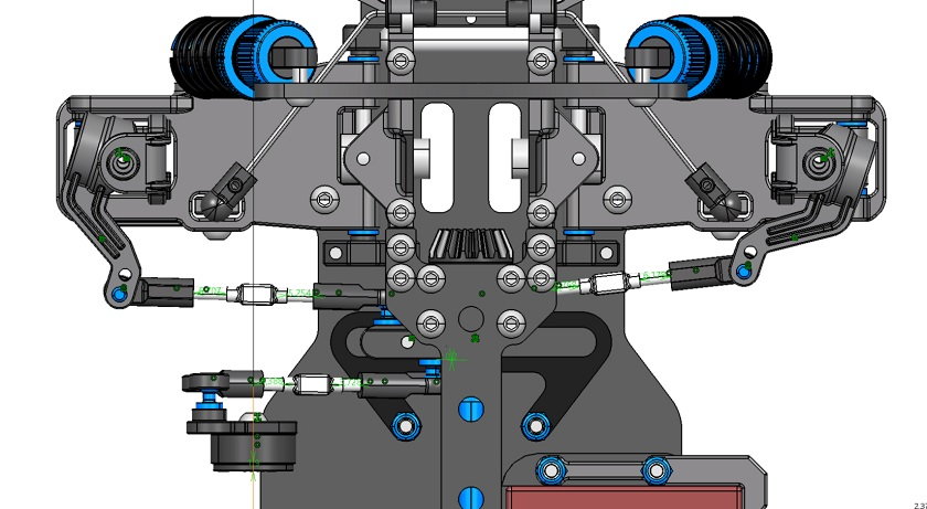
This is the second option. Very similat to the one I use on the buggy I designed 10 years ago. And it worked fine. This option is not already finished. I still having a little space to play but not much
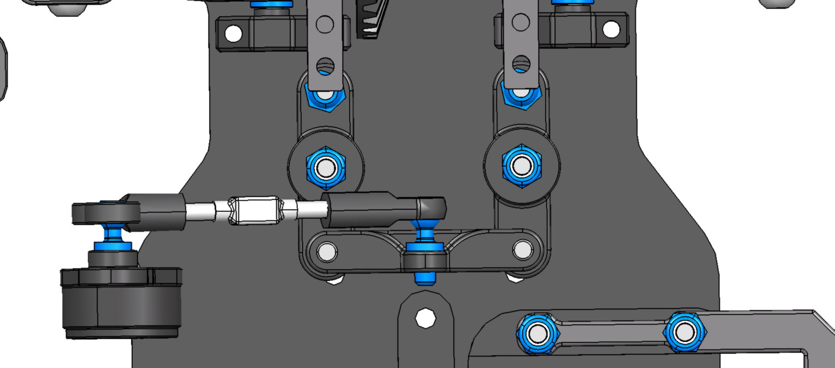
I investigate about a lineal steeringn too, but I have no experience with this kind of steering.
This is the second option. Very similat to the one I use on the buggy I designed 10 years ago. And it worked fine. This option is not already finished. I still having a little space to play but not much
I investigate about a lineal steeringn too, but I have no experience with this kind of steering.
04-18-2020, 01:33 PM
#22
The lineal steering looks like not bad idea.
04-18-2020, 02:15 PM
#23
Looks nice, but can it work with two ball bearings without resistance? These would not turn, just slide. Am I missing something 
04-18-2020, 08:54 PM
#25
Tech Master
AMX has the linear steer. It worked. I dont like it as much as conventional but it worked. It went through allot of revisions though. You might want to look at those revisions to get a feel for the issues. It did go from bushings to roller bearings. The clearances had to be pretty tight to keep the slop out and you need to be able to adjust the preload on the bearings to keep the slop out.
04-18-2020, 09:21 PM
#26
It will steer as long as a piece of debris or tiny piece of asphalt gravel does not fall in there. TC3's had that problem happening in outdoor parking tracks.
04-19-2020, 05:40 AM
#27
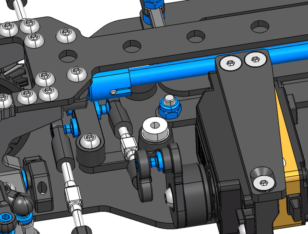
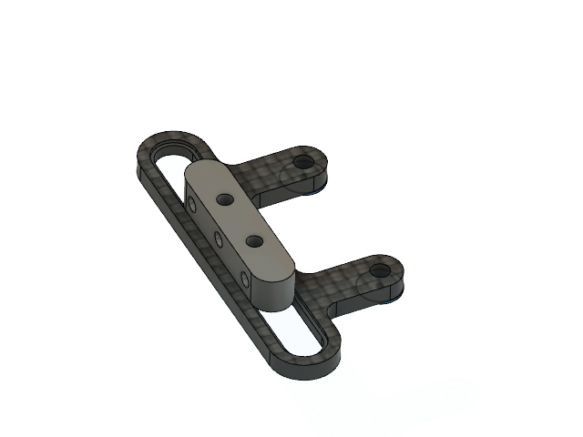
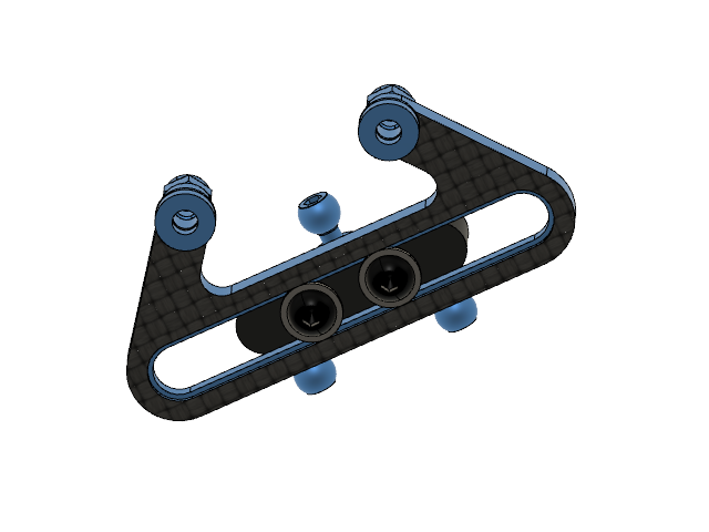
This is the best design to avoid collision between the ball end and the steering plate (And keep using the same holes from the chasis  )
)
)
Last edited by Eotz; 04-19-2020 at 10:19 AM.
04-20-2020, 03:19 AM
#28
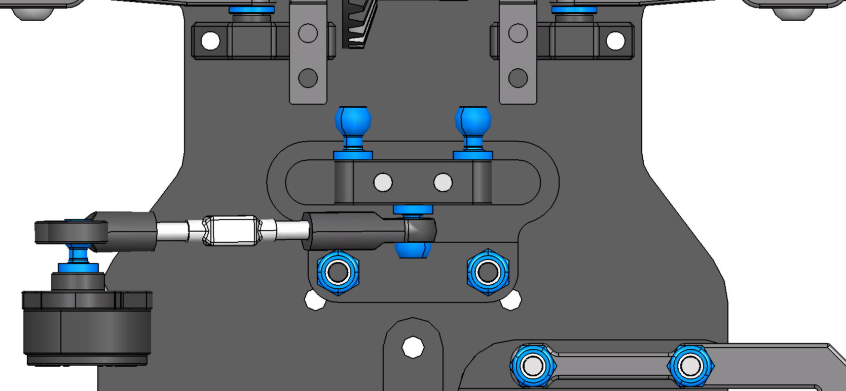
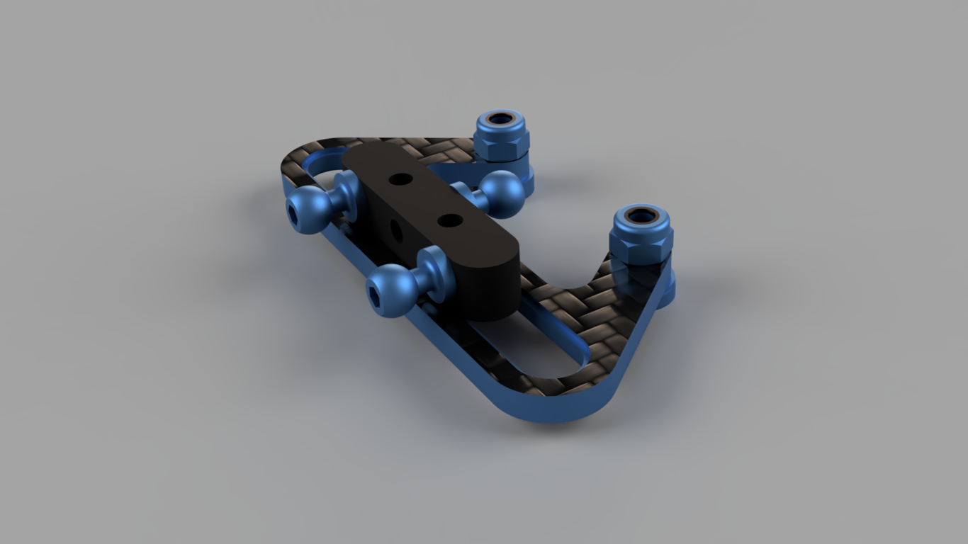
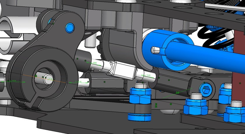
The kinematic look also fine. I have margin for small improvements and made the carbon fiber smaller (reduce the slot for the bearings 5mm on both sides) but that is more or less the final look. The best point of this kind of steering is that use less parts.
As I say before, the gaps between all the parts are very narrow and I will have to fine tune the transmitter dual rate.
As I say before, the gaps between all the parts are very narrow and I will have to fine tune the transmitter dual rate.
04-20-2020, 06:12 AM
#29
I have a question regarding steering design in general. But particularly with shaft drive.
Why does every design have the linkage from the servo attached at the center of the steering bridge? I understand that it “equalizes” the force exerted in both directions, and helps with torque output from the servo. But with modern design programs and the strength of available materials, along with the power than modern servos output, why not shorten the link and attach it to the side closest to the servo? This would all but eliminate the possibility of the steering coming into contact with the drivetrain.
Why does every design have the linkage from the servo attached at the center of the steering bridge? I understand that it “equalizes” the force exerted in both directions, and helps with torque output from the servo. But with modern design programs and the strength of available materials, along with the power than modern servos output, why not shorten the link and attach it to the side closest to the servo? This would all but eliminate the possibility of the steering coming into contact with the drivetrain.
04-20-2020, 06:41 AM
#30
I have a question regarding steering design in general. But particularly with shaft drive.
Why does every design have the linkage from the servo attached at the center of the steering bridge? I understand that it “equalizes” the force exerted in both directions, and helps with torque output from the servo. But with modern design programs and the strength of available materials, along with the power than modern servos output, why not shorten the link and attach it to the side closest to the servo? This would all but eliminate the possibility of the steering coming into contact with the drivetrain.
Why does every design have the linkage from the servo attached at the center of the steering bridge? I understand that it “equalizes” the force exerted in both directions, and helps with torque output from the servo. But with modern design programs and the strength of available materials, along with the power than modern servos output, why not shorten the link and attach it to the side closest to the servo? This would all but eliminate the possibility of the steering coming into contact with the drivetrain.
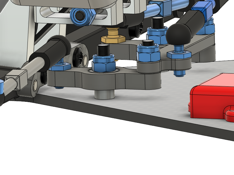
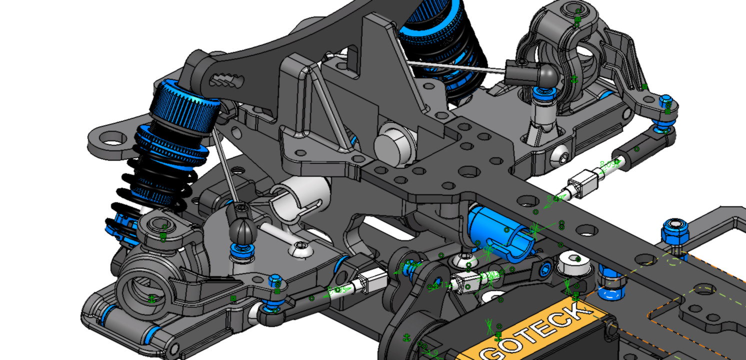
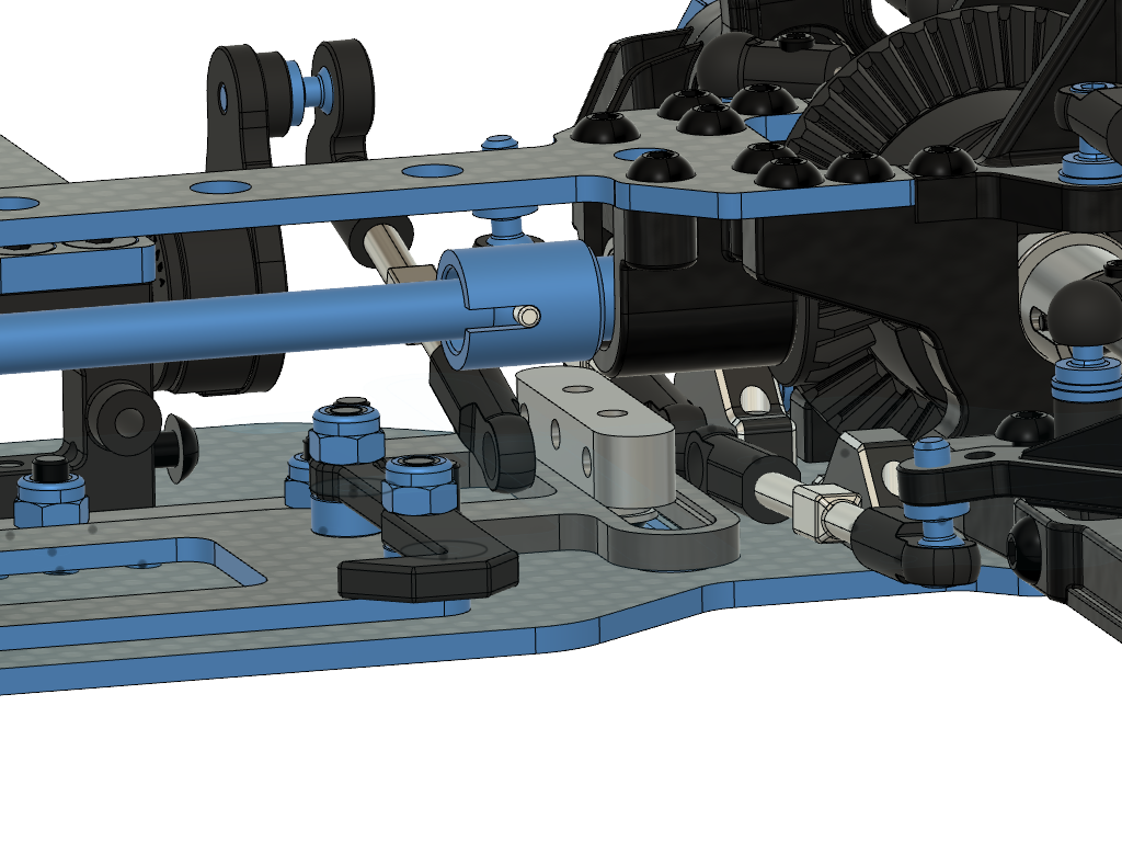
So, I can't connect the servo to the opposite side of the bridge like in the picture above because of the shaft, and is difficult to do it a the servo side because there is too little place for the link. So the best solution seems to be the middle.