


 57Likes
"Load Master"

 06-22-2023 | 10:16 AM
#32
I picked up my Load Master yesterday. Looks well made. Hoping to try it out later today. I also picked up a R1 Digital 3 ESC. I’m hoping to get it installed for this weekends race and start generating some real world numbers for a 21.5t TC on an asphalt track.
06-24-2023 | 10:01 PM
#33
I have figured out how to measure timing. Now it is a matter of writing the code for it. The back emf of the motor is not dependent on timing, whereas the hall sensors obviously are. So to measure timing you need the delta between the rising edge of the sensor pulse and the rising edge of the back emf. Here are a couple of scope pics that I did. The first one the can timing on the motor is set to 0*, you can see that the rising edge of the back emf and the sensor line up. The second pic has timing advance of about 40*, you can see that the back emf lags behind the sensor.


06-26-2023 | 10:21 AM
#34
If you want to bounce any ideas off someone, let me know. I've done a decent number of custom boards using microcontrollers. Some general suggestions - I'd use something more modern than a 328P. There are AVR devices with better internal peripherals, more flexible and simpler to implement that cost half the price. Not quite sure how you'd establish timing from the sensor signals alone, since they'll always have a fixed relationship relative to each other.
06-26-2023 | 03:42 PM
#35
What is your opinion on the RA4M1 mcu? Granted the chip is more expensive than the 328p, but it offers up to 3x the clock speed and a lot more memory. Which would be nice since I like using the oled displays but they are memory hogs. I would like to stay with 5v vcc instead of moving to 3.3v, so I am interested in this chip. I am going to order an uno 4 for testing. Also as a huge bonus, it has a 14 bit adc instead of 10 bit. Which will be nice because another project I am working on I am adding an mcp 3204, which is a 12 bit.
06-26-2023 | 08:26 PM
#36
So I guess, back to struggling with timing... The issue is the calculations I make don't come close to the Trinity Motolyser. While the calculations do increase and decrease when changing the timing on a motor and compare across motors, the values are off and not by the same coefficient. I am attaching screen shots of 3 different motors. The first is an v21s (21.5), the second a slot machine (21.5) and the third an mc4 (17.5).
Trinity Motolyser readings are as follows:
v21s - 42.1*
SM - 45.2*
mc4 - 38.9*
My calculated values:
v21s - 56.5*
SM - 58.2*
mc4 - 56.1*
The measurements are done vs sensor c and phase c
My calculation is (1/frequency of motor)/360 to get degrees per second. Then take the time difference between the rising edge of the hall sensor - the guestimated zero cross of the bemf on phase c. The zero cross will be about halfway through the first small rise. The output is only showing half the bemf wave. The cursors in the pic show where I am calculating from and the delta is calculated by the scope.
Anyway, delta time/ degrees per second = degrees timing.
What am I missing here? I can use comparators to get a real zero cross, but I doubt it will account for 15-20* difference. And if that number just stayed the same, it would be easy.
R1 v21s 21.5

Trinity Slot Machine 21.5

Motiv MC4 17.5

Trinity Motolyser readings are as follows:
v21s - 42.1*
SM - 45.2*
mc4 - 38.9*
My calculated values:
v21s - 56.5*
SM - 58.2*
mc4 - 56.1*
The measurements are done vs sensor c and phase c
My calculation is (1/frequency of motor)/360 to get degrees per second. Then take the time difference between the rising edge of the hall sensor - the guestimated zero cross of the bemf on phase c. The zero cross will be about halfway through the first small rise. The output is only showing half the bemf wave. The cursors in the pic show where I am calculating from and the delta is calculated by the scope.
Anyway, delta time/ degrees per second = degrees timing.
What am I missing here? I can use comparators to get a real zero cross, but I doubt it will account for 15-20* difference. And if that number just stayed the same, it would be easy.
R1 v21s 21.5
Trinity Slot Machine 21.5
Motiv MC4 17.5
06-27-2023 | 12:26 AM
#37
It wouldn't surprise me if the method of measuring the rising edge would account for such a big delta. I've seen massive variances (15+ degrees) just between a SkyRC analyser vs a Hobbywing Tunalyzer. Though maybe they're also using different algorithms to compute the value.
Your back EMF signal looks pretty isolated. Are you measuring this on the slave motor? I'd expect the timing delta to be different on the driven motor. The EMF distorts as the motor rotates. There's also the winding time, which should be a fixed lag caused by the inductance of the stator. I'd expect the field distortion to be similar on the master vs slave, but the winding time might be an offset in the other direction since it's a lag of the input vs output.
https://pphaneuf.github.io/rccars/ar...timing-theory/
Does your margin of error vs the Motolyser decrease as the RPM is reduced?
06-27-2023 | 06:20 AM
#38
It wouldn't surprise me if the method of measuring the rising edge would account for such a big delta. I've seen massive variances (15+ degrees) just between a SkyRC analyser vs a Hobbywing Tunalyzer. Though maybe they're also using different algorithms to compute the value.
Your back EMF signal looks pretty isolated. Are you measuring this on the slave motor? I'd expect the timing delta to be different on the driven motor. The EMF distorts as the motor rotates. There's also the winding time, which should be a fixed lag caused by the inductance of the stator. I'd expect the field distortion to be similar on the master vs slave, but the winding time might be an offset in the other direction since it's a lag of the input vs output.
https://pphaneuf.github.io/rccars/ar...timing-theory/
Does your margin of error vs the Motolyser decrease as the RPM is reduced?
Your back EMF signal looks pretty isolated. Are you measuring this on the slave motor? I'd expect the timing delta to be different on the driven motor. The EMF distorts as the motor rotates. There's also the winding time, which should be a fixed lag caused by the inductance of the stator. I'd expect the field distortion to be similar on the master vs slave, but the winding time might be an offset in the other direction since it's a lag of the input vs output.
https://pphaneuf.github.io/rccars/ar...timing-theory/
Does your margin of error vs the Motolyser decrease as the RPM is reduced?
As to the scope output, I have played around with different grounding points to see what gives the easiest output to trigger on. When using the virtual common ground between the phases it is extremely hard to trigger on the wave, but you do see the alternating voltage that way. The way I am measuring in the pics above is to use the ground on the rpm sensor and trigger on that. That square wave is easy to trigger on so it stabilizes the emf wave to read, but since the grounding is different, you only see part of the wave. If I use the virtual common, the rpm sensor wave is distorted and harder to trigger on. I have measured the intervals using the virtual common as well, and they are the same.
EDIT: For clarity, the virtual common is created by using a 10k resistor off each of the phases and connected together, creating a virtual common between each of the phases.
If inductance was playing a role, I would expect the 17.5 to have a smaller margin of error vs the 21.5 since the 17.5 has lower inductance. Also, I am not sure how the motolyser would account for that since that would change with each motor.
I did order some lm339 comparators to use for getting a more accurate zero cross, I tried using the internal comparator on the arduino, but I think my code was wrong.
EDIT: I tested my slot machine 13.5, certified slot machine 21.5, and my other R1 to compare. The slot machine and the v21s all have on offset of 17-18* throughout the timing range. It is only the mc4 that is higher. I need some other brands of motors to test with...
Last edited by trilerian; 06-27-2023 at 06:53 AM.
06-27-2023 | 07:38 AM
#39
Tech Lord

Joined: Aug 2007
Posts: 14,052
From: Holland
Maybe this topic will help: Non-timing "Blinky" ESC Test Using an Oscilloscope - R/C Tech Forums (rctech.net)
And here some vids:
Pole Position RC Club | Facebook
And here some vids:
Pole Position RC Club | Facebook
Last edited by Roelof; 06-27-2023 at 07:52 AM.
06-27-2023 | 08:56 AM
#40
Maybe this topic will help: Non-timing "Blinky" ESC Test Using an Oscilloscope - R/C Tech Forums (rctech.net)
And here some vids:
Pole Position RC Club | Facebook
And here some vids:
Pole Position RC Club | Facebook
I had a look through that, thanks. It looks like the setup he is using is similar, we are both triggering on the hall sensors then looking at the rising edge of the hall sensor compared to the motor signal. The only difference is he changing the x axis, where I like to see the complete waveform. A big difference though is that I have been using the motolyser to run my tests and not an esc. So I tried using my hobbywing xr10 pro. The output for the motor looks easier to work with, more comparable to a square wave at full throttle, which I should be able to read with the arduino on a digital input. I measured a few motors and they all seem about 20* off, so that just may be my offset I program in. Here is a pic using the xr10 pro. And now, I'll need to test on other esc's and motors...

EDIT:
It was really cool being able to see amp draw, rpm, voltage, and "sort of" timing without using a motolyser.
EDIT: After running a 17.5 and a 13.5 the waveform looks more trapezoidal. So I will need to use a comparator still.
Last edited by trilerian; 06-27-2023 at 09:45 AM.


 07-02-2023 | 02:37 PM
#42
So I have cobbled together some code using the internal comparator in the 328p chip and managed to get digital waves out of the bemf. Now my brain hurts because I learned how to use the port registers directly instead of doing digital read on pin yadda, yadda... Anyway, as you increase or decrease timing the digital waves correspond so that is something. I now need to reinvent my rpm counter using port registers and then setup a comparison between the bemf and the rpm. Attached is a pic that has the 3 bemf waves plus one rpm sensor output. The bottom waveform is the rpm sensor.

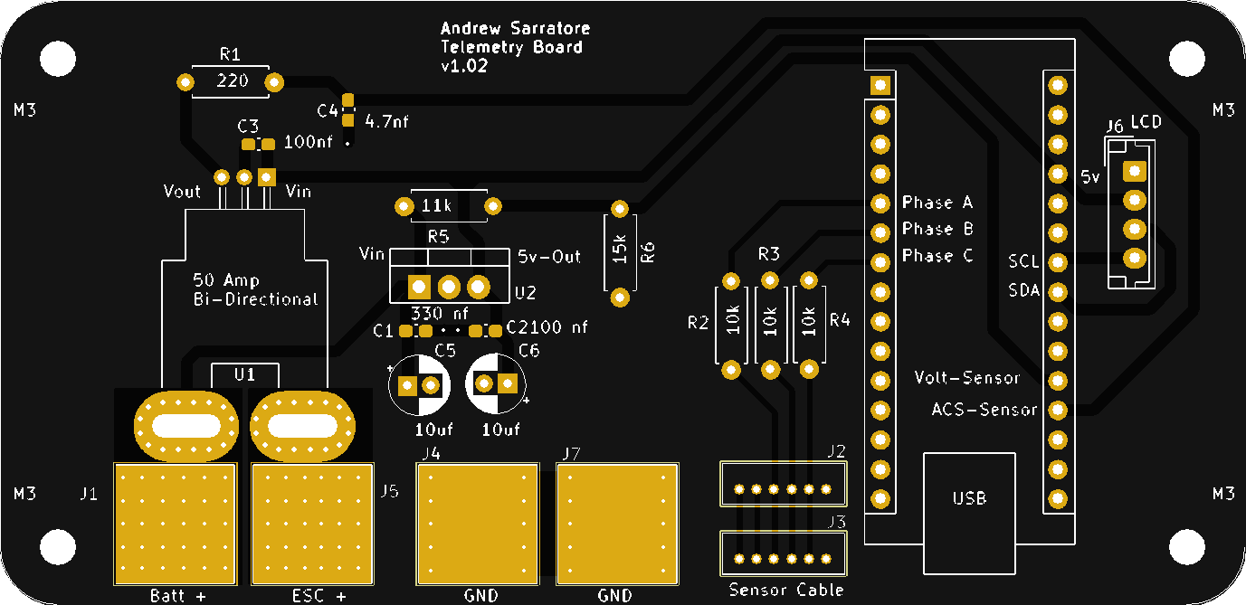
07-09-2023 | 12:31 PM
#43
Here is my initial design on implementing the telemetry sensor unit with the Load Master. So with this you don't need a motor analyser, just an esc to run it.
This is going to take about 15 hours to print on my small printer, so I would like feedback before I proceed. The front is open to allow for sensor harness connection, battery and esc wires and a usb to the arduino nano for possible updates.

This is going to take about 15 hours to print on my small printer, so I would like feedback before I proceed. The front is open to allow for sensor harness connection, battery and esc wires and a usb to the arduino nano for possible updates.
