


Non-timing "Blinky" ESC Test Using an Oscilloscope
 02-24-2016 | 05:57 AM
#1
Here's an interesting and thorough set of videos by Big Chuck Kleinhagen showing how to check ESCs for non-timing "Blinky" operation. Chuck, owner of Fastlane Raceway, is also the organizer for the Brushless Racing League oval racing series.
https://www.youtube.com/watch?v=UOu42ywJ21I
https://www.youtube.com/watch?v=-IVlGhX4IZs
https://www.youtube.com/watch?v=MlM4HIJjiX8
https://www.youtube.com/watch?v=xFOJYhF9JkE
I want to thank Chuck for doing these-- he is a really busy guy, but still took the time to record these for us. Since he is a very busy guy, please don't contact him regarding the videos; I'll try to answer any questions here, in this thread.
Part 1 shows connections to the sensor cable. Chuck is using an sensor cable adapter that I made for him, but it's not absolutely necessary to do the test.
Part 2 covers scope setup. You can skip this is you are familiar with oscilloscopes.
Part 3 shows the actual test. If you only watch one of the videos, this should be the one.
Part 4 is an addendum addressing what's important and what can be ignored on the oscilloscope display.
 02-24-2016 | 07:34 AM
#2
Tech Lord

Joined: Aug 2007
Posts: 14,052
From: Holland
I believe at the worlds here in Holland a few years ago they also did something simulair. Funny is that using those 2 signals with a small uProsessor like an arduino you could measure the timing between those 2 and make a readout on a small display. Why isn't that devellopped yet?
02-24-2016 | 07:42 AM
#3
I believe at the worlds here in Holland a few years ago they also did something simulair. Funny is that using those 2 signals with a small uProsessor like an arduino you could measure the timing between those 2 and make a readout on a small display. Why isn't that devellopped yet?
 02-24-2016 | 10:13 AM
#4
Tech Lord
Joined: Aug 2007
Posts: 14,052
From: Holland
I know a lot of electronics but know nothing of programming uP's (although I do know what is possible with them), I have a Arduino starterskit to start with but have still so many other things to do in my mind....
Basically a simple phase detector should be able to detect a positive/negative timing and that can be done with some simple logic components.
On the other hand, a simple DSO201 oscilloscope is very affordable and easy to transport.
Basically a simple phase detector should be able to detect a positive/negative timing and that can be done with some simple logic components.
On the other hand, a simple DSO201 oscilloscope is very affordable and easy to transport.
02-24-2016 | 12:08 PM
#5
I know a lot of electronics but know nothing of programming uP's (although I do know what is possible with them), I have a Arduino starterskit to start with but have still so many other things to do in my mind....
Basically a simple phase detector should be able to detect a positive/negative timing and that can be done with some simple logic components.
On the other hand, a simple DSO201 oscilloscope is very affordable and easy to transport.
Basically a simple phase detector should be able to detect a positive/negative timing and that can be done with some simple logic components.
On the other hand, a simple DSO201 oscilloscope is very affordable and easy to transport.
02-25-2016 | 02:19 AM
#7
Tech Lord
Joined: Aug 2007
Posts: 14,052
From: Holland
The pinout:
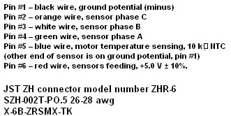
I also made a sensor adapter for my FDR meter:
With on the rear large surfaces voor power and 1 sensor signal:
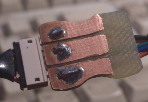
I used plain circuit board (I buy scrap material for a few bucks, also handy to make small epoxy parts). This was a first attempt, later ones were done on a mill with a digital readout with better results.
I have got a small and thin dremel tool like sawblade from Proxxon:
http://www.conrad.com/ce/en/product/...CRO-Cutter-MIC
Making grooves in the copper layer at a 1.5mm distance you can make the adapter plate.
I also made a sensor adapter for my FDR meter:
With on the rear large surfaces voor power and 1 sensor signal:
I used plain circuit board (I buy scrap material for a few bucks, also handy to make small epoxy parts). This was a first attempt, later ones were done on a mill with a digital readout with better results.
I have got a small and thin dremel tool like sawblade from Proxxon:
http://www.conrad.com/ce/en/product/...CRO-Cutter-MIC
Making grooves in the copper layer at a 1.5mm distance you can make the adapter plate.
02-25-2016 | 12:42 PM
#9
The adapter is just a through connection, with pin 1 on the first connector wired to pin 1 on the second connector, pin 2 to pin 2, and so on, for all six connections. I used a spare circuit board from an inline dynamic timing boost module I designed many years ago because it already had holes and traces for the two connectors. Then I added some 0.025" square post connectors on perfboard to bring out all three sensor signals and a pair of grounds.
Chuck mentioned in the video that he always plugs the ESC and the motor into the ends of the adapter marked "ESC" and "MOT", but the adapter really doesn't have a "direction", so the cables could be swapped and still function properly.
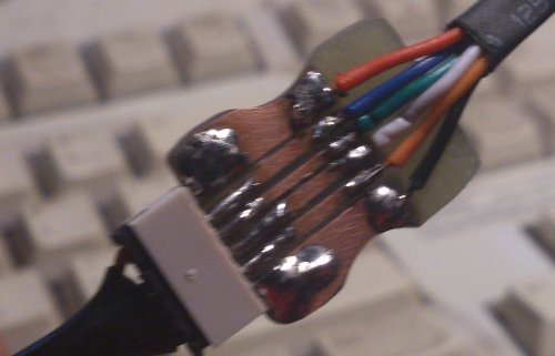
As Roelof has shown, there are other ways to gain access to the necessary signals. I'll show another example below. It is simply a spare sensor cable with the ground and Sensor B wires cut, stripped, twisted, and soldered back together, with the wires formed into small loops for the scope probes to grab onto. Ground is pin 1, which is on the left side of the connector if the wires are facing up and the metal crimp connectors are visible. The Sensor B signal is on the third wire from the left:


It's a good idea to space the loops apart from each other with a plastic or wood insulator so they don't short out.
Chuck mentioned in the video that he always plugs the ESC and the motor into the ends of the adapter marked "ESC" and "MOT", but the adapter really doesn't have a "direction", so the cables could be swapped and still function properly.
As Roelof has shown, there are other ways to gain access to the necessary signals. I'll show another example below. It is simply a spare sensor cable with the ground and Sensor B wires cut, stripped, twisted, and soldered back together, with the wires formed into small loops for the scope probes to grab onto. Ground is pin 1, which is on the left side of the connector if the wires are facing up and the metal crimp connectors are visible. The Sensor B signal is on the third wire from the left:
It's a good idea to space the loops apart from each other with a plastic or wood insulator so they don't short out.
02-25-2016 | 03:15 PM
#10
I recently acquired a new DSO203 (a.k.a. DS203) "pocket oscilloscope" from the evil auction site for less than $160 shipped (from the USA!). This was the least expensive model I could find with enough bandwidth-- 8MHz-- to do the ESC timing test. I wouldn't recommend this as a general-purpose oscilloscope, since the screen is very small, the voltage levels aren't very accurate, and the user interface is too cumbersome. But for this particular job it works pretty well.
The scope settings below are for the DSO203, but will be similar for other scopes. One problem with the DSO203 is that I have not found a way to tell it that its probes are on their 10X setting; when the scope says 0.2V/division, it's really at 2.0V/division with a 10X probe.
Set the scope probes to 10X.
Set channels A and B to DC coupling and 0.2V/division (which is actually 2V per division since the probes are set to 10X).
Turn off channels C and D.
Set the trigger for Auto mode, using channel A's rising edge, and the trigger threshhold to 200mV (which is actually 2V since the probe is set to 10X).
Set the vertical position for channels A and B so they can be easily seen; I put the channel A baseline at one major grid division above center, and the channel B baseline at one major division above the bottom of the screen.
Set the horizontal time base to 2us/division, and the horizontal position to a few divisions left of the screen center.
When you have made all of the above changes to the scope settings, save the settings so they are retained when the scope is turned off. Most scopes do this automatically, but the DSO203 requires a special effort (press the square key, use the left/right arrow switch to select "Save Param", then press down on the "+ -" key).
To do the test:
Make sure the power switch on the car is OFF.
Set the car on a stand so the tires can spin freely, and not tangle with any wires.
Remove the exisiting sensor cable and replace it with the test sensor cable.
Connect both scope ground (alligator) clips to the ground connection on the test sensor cable.
Connect the Channel A probe to the Sensor B connection on the test sensor cable.
Power up the transmitter and the car.
Connect the Channel B probe to the motor's C terminal.
Apply full throttle.
The sensor signal will be displayed on Channel A of the scope, and the motor drive on Channel B. The drive must change after the sensor change; this will be to the right of the sensor change on the oscilloscope screen, since time is displayed from left to right. If the motor drive changes before the sensor, that's timing advance (which is not allowed in "Blinky").
ROAR requires that the motor drive change no later than 10us after the sensor change. Some older ESCs have somewhat more delay than that, but in general they won't exceed 20 us or so.
When the test is complete, turn off the power on the car, remove the test sensor cable, and replace the original sensor cable.
Last edited by howardcano; 02-25-2016 at 03:35 PM.
02-25-2016 | 11:42 PM
#11
Tech Lord
Joined: Aug 2007
Posts: 14,052
From: Holland
At www.DX.com these DSO scopes are affordable to find.
But it seems that a portable setup can be made.
But it seems that a portable setup can be made.
 04-25-2016 | 07:56 PM
#14
I've been using one of these scopes for testing amps. Using a laptop with a 17in screen is a little easier than the little all in ones.
http://www.amazon.com/Hantek-Digital.../dp/B009H4AYII
The better open source software is somewhere in this thread...
http://www.eevblog.com/forum/testgea...z-usb-dso/630/
http://www.amazon.com/Hantek-Digital.../dp/B009H4AYII
The better open source software is somewhere in this thread...
http://www.eevblog.com/forum/testgea...z-usb-dso/630/
04-26-2016 | 02:56 AM
#15
I've been using one of these scopes for testing amps. Using a laptop with a 17in screen is a little easier than the little all in ones.
http://www.amazon.com/Hantek-Digital.../dp/B009H4AYII
The better open source software is somewhere in this thread...
http://www.eevblog.com/forum/testgea...z-usb-dso/630/
http://www.amazon.com/Hantek-Digital.../dp/B009H4AYII
The better open source software is somewhere in this thread...
http://www.eevblog.com/forum/testgea...z-usb-dso/630/
Last edited by howardcano; 04-26-2016 at 03:09 AM.