


 3Likes
Transponder Design
 01-26-2013 | 03:28 AM
#106

Do you think this would be improved by reducing the slew rate on the driver? If I am not mistaken the maximum frequency component (ideal) would be 6.25MHz. so even a 2nd order LPF would have no issue at all killing off the higher frequency component. or am I missing something entirely?
No matter, it passed. I've had my own designs pass by a lower margin, but we usually tested at least one more sample when that happened to give some indication that tolerance wouldn't push production units over the limit.
 01-30-2013 | 07:07 AM
#107
Here�s the status of my transponder design:
I now have all of the circuit boards populated, and tested them last night. Most of them have the same program, containing a single ID number that I will use on all of my cars (there are so many of them!). So, one of my goals for the project has been met: create cheap transponders that I can leave in each car, eliminating the hassle of moving a transponder from car to car. (The same ID number will also make things a bit easier for the person running the scoring PC when I�m running multiple classes, as my information will only need to be entered once.) I�ll also retain the AMB transponder that has this ID number.
I also made a couple of boards with different ID numbers for use in my �loaner� cars that I let other drivers race in our Breakout class at the local track.
The second goal, having a design that might be commercially viable, is nearly complete. To this end, I tested the new program for the PIC12F683 that contains multiple ID numbers. There are currently 25 numbers that I code-compressed, and most of them operated correctly. The ones that did not function had obvious errors (in hindsight!), and they are now fixed and ready to re-test. (Hopefully there will be time to do that this Sunday.)
The ID selection is pretty simple: power-down, place a jumper on the 2-pin connector (or short the pins with a metal object), and power-up to step to the next selection. If the jumper is left on the 2-pin connector, then the microprocessor loads a new number each time power is applied, which makes my testing pretty easy�turn the car on, run it twice over the timing loop, record the result given by the scoring PC, then turn the car off and on again to test the next number.
There is, however, no indication of which ID number is selected on the transponder, so it might be a good idea to add some code to blink the LED in an appropriate pattern whenever a new ID number is selected. One to four blinks to indicate the ID set, and one to eight blinks to indicate the selection within the set, would work quite nicely for the 32 ID numbers that will fit into the 12F683. It will also be easy to increase from four to eight sets (as there is a PIC12F microprocessor currently available with a larger memory that would hold perhaps 64 ID numbers).
I�ve got several more transponders on the way, and will fill up the remaining ID number memory as time permits, but other than that I think I�ve reached a reasonable stopping point.
It�s time to try the loop amplifier design for the decoder!
 01-30-2013 | 10:07 AM
#109
http://www.rctech.net/forum/11708230-post67.html
I may pursue selling the design to an individual or company that wants to produce these, but I have no news on that right now.
Yes, I can "clone" numbers. That's the only way I can create programs at the moment, since I have no idea of the data format used by AMB.
02-06-2013 | 01:35 AM
#111
Here are some photos of the tranponders in a few of my cars. They illustrate the size of the transponder, 1.25" square, in its current, through-hole form. The first shows an HPI 235mm-wide HPI 1/10 scale pan car that I use in our local Breakout class. Plenty of room here:

Here's a 200mm-wide SpeedMerchant WGT car, still with plenty of space:

I had to mount the transponder on top of the steering servo on my XRay T1 VTA car (the smaller AMB transponder was on the chassis directly on front of the receiver):

When we get to a 1/12 scale car, this Carpet Knife 3.2, things start to look ridiculous, but it does barely fit, and still makes minimum weight:

Here's a 200mm-wide SpeedMerchant WGT car, still with plenty of space:
I had to mount the transponder on top of the steering servo on my XRay T1 VTA car (the smaller AMB transponder was on the chassis directly on front of the receiver):
When we get to a 1/12 scale car, this Carpet Knife 3.2, things start to look ridiculous, but it does barely fit, and still makes minimum weight:
02-13-2013 | 07:50 AM
#112
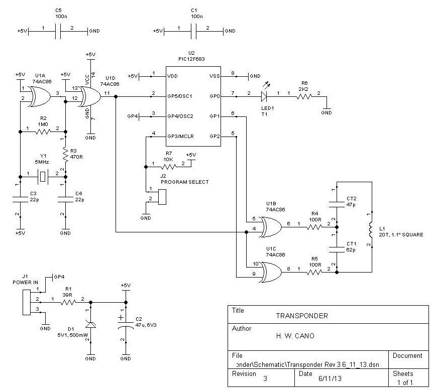
I updated the schematic using TinyCAD. If anyone wants to lay out a smaller, surface-mount PCB, I can PM a netlist to you. I would suggest using four layers, both for ease of routing and to make the tank inductor dimensionally smaller (since it can have turns on all layers). Remember, NO POWER OR GROUND PLANES ARE ALLOWED, as they would keep the inductor from radiating the necessary magnetic field!
The design now includes a Zener diode to permit operation from 5V to 6.6V (a 2-cell LiFe or 5-cell NiMH receiver pack).
U1D may be eliminated if single-gate packages are used.
The design now includes a Zener diode to permit operation from 5V to 6.6V (a 2-cell LiFe or 5-cell NiMH receiver pack).
U1D may be eliminated if single-gate packages are used.
Last edited by howardcano; 06-11-2013 at 07:36 AM. Reason: Included note on U1D. Updated values for R1 and R6.
02-13-2013 | 11:18 AM
#113
Tech Initiate
Joined: Feb 2013
Posts: 29
Hi Howard,
i have seen several schematics where oscillator freq is sourced form osc2 output of pic.
Xtal is connected between osc1 and osc2 and you can source freq from osc2 as it is output of internal gate. With such configuration you can save U1A, U1D and R2.
i have seen several schematics where oscillator freq is sourced form osc2 output of pic.
Xtal is connected between osc1 and osc2 and you can source freq from osc2 as it is output of internal gate. With such configuration you can save U1A, U1D and R2.
02-13-2013 | 11:36 AM
#114
It would be even nicer to use the internal RC oscillator, but the accuracy and temperature drift eliminate that option.
Last edited by howardcano; 02-13-2013 at 11:49 AM.
02-14-2013 | 04:41 AM
#116
Tech Initiate
iTrader: (1)
Joined: Aug 2006
Posts: 34
I think that for the SMD version an ICSP connector can be really comfortable.
Why GP4 is connected to the power connector ? Debugging purposes or additional features ?
Last question, why do you put a rubber band in the steering of your pan cars ?
?
Why GP4 is connected to the power connector ? Debugging purposes or additional features ?
Last question, why do you put a rubber band in the steering of your pan cars
?
02-14-2013 | 05:10 AM
#117
That removes the slop from the ball joints. It has the advantage that when I hit something and add to the slop, it is immediately taken up by the rubber band. I use rubber bands on all of my cars, not just the pan cars.
02-14-2013 | 11:02 AM
#119
EDIT: Changing R1 to 100 ohms will also do the trick, but then the minimum voltage required for operation will be about 6V.
Last edited by howardcano; 02-15-2013 at 02:07 AM.
03-17-2013 | 08:14 AM
#120
Tech Adept
Joined: Feb 2003
Posts: 147
If you have the design already debugged and tested, I would be happy to help with a surface mount layout. I already have done SMD designs of ESC for RC cars using four layer PCBs.
I am not interested in adding an LDO into the transponder design. What I am interested in would be an open source design alternative to the AMB units, with the power supplied by the existing BEC in the ESC.
Anyway, I would be happy to do the SMD PCB layout as long as this design will continue to be an open source project to benefit the RC racing hobby and community.