Transponder Design
#121
A couple months ago I took a piece of wire, wrapped it around my transponder a few times, and hooked it up to an oscilloscope. Glad to see someone with much more engineering experience and know-how than myself had the same idea  Unfortunately I wasn't able to take it much further than figuring out what the signal looked like as I have very little experience with circuit design or RF transmission. Reading your thread has been a great learning experience and provided me with enough tidbits of info to build my own clone.
As an aside, I got into engineering by building DIY guitar pedals from schematics online when I was in high school. I remember seeing the name Cano in quite a few designs and I may have even built one. Small world.
 Unfortunately I wasn't able to take it much further than figuring out what the signal looked like as I have very little experience with circuit design or RF transmission. Reading your thread has been a great learning experience and provided me with enough tidbits of info to build my own clone.
 As an aside, I got into engineering by building DIY guitar pedals from schematics online when I was in high school. I remember seeing the name Cano in quite a few designs and I may have even built one. Small world.

#122
If you have the design already debugged and tested, I would be happy to help with a surface mount layout. I already have done SMD designs of ESC for RC cars using four layer PCBs.
I am not interested in adding an LDO into the transponder design. What I am interested in would be an open source design alternative to the AMB units, with the power supplied by the existing BEC in the ESC.
Anyway, I would be happy to do the SMD PCB layout as long as this design will continue to be an open source project to benefit the RC racing hobby and community.
Using four or more layers will let you add more turns to the tank inductor, making it possible to shrink the external dimensions but still maintain approximately the same inductance. You'll probably need to adjust the tank capacitors for tuning and Q with the new inductor.
Everyone is free to use all of the information that has been presented so far in this thread (and my decoder thread). The only item that is not open-source at the moment is the program, but I offer programmed microprocessors at a nominal fee (to help recover some of my development costs). If anyone wants to go into production, we can work out a licensing arrangement. I understand that RCTech user Payalneg has already written his own software to run on an Atmel microprocessor, so that is another viable option. RC10Nick also seems to have also done his own software (see his previous post).
Last edited by howardcano; 03-18-2013 at 06:26 AM.
#123
A couple months ago I took a piece of wire, wrapped it around my transponder a few times, and hooked it up to an oscilloscope. Glad to see someone with much more engineering experience and know-how than myself had the same idea  Unfortunately I wasn't able to take it much further than figuring out what the signal looked like as I have very little experience with circuit design or RF transmission. Reading your thread has been a great learning experience and provided me with enough tidbits of info to build my own clone.
As an aside, I got into engineering by building DIY guitar pedals from schematics online when I was in high school. I remember seeing the name Cano in quite a few designs and I may have even built one. Small world.
 Unfortunately I wasn't able to take it much further than figuring out what the signal looked like as I have very little experience with circuit design or RF transmission. Reading your thread has been a great learning experience and provided me with enough tidbits of info to build my own clone.
 As an aside, I got into engineering by building DIY guitar pedals from schematics online when I was in high school. I remember seeing the name Cano in quite a few designs and I may have even built one. Small world.

I’ve had a few people recognize my name from my synthesizer and MIDI designs, and my articles in Electronic Musician magazine. For those of you that have similar interests, I gave links to a few of my creations in the following post. (Photobucket has recently “improved” their web site, so now the photos are no longer in correct order; I’ll fix that as soon as Photobucket restores the capability.)
http://www.rctech.net/forum/11612745-post24.html
On a more related path, some people have also recognized my name from my articles in RC Modeler, RC Model Cars, and Model Builder magazines (again, the photos are no longer in the proper sequence):
http://s1191.beta.photobucket.com/us...54640696489777
Last edited by howardcano; 03-18-2013 at 06:23 AM.
#125
If I ever do find time to follow through with this project I imagine I'd follow the same path as you with my software. I'd rather not give out cloned copies of my own PT number.
Again, thank you for sharing your knowledge.
#126
Here’s a quick update on the transponder design:
I have now used my transponders for several months, with excellent results. Then, about two weeks ago, we ran into a problem with intermittent counting on all of my transponders (which are installed in about half of the cars running in our Breakout class), and my single remaining MRT transponder. The track’s AMB decoder was unchanged. As a further point of intrigue, my original AMB transponder (from which I had “cloned” the ID number for my own transponders) also indicated “INVALID TRANSPONDER” on the scoring computer! We swapped out transponders and rebooted the computer, and ran the rest of the day without problems.
It is unknown why this problem suddenly occurred, but I suspect that the software on the scoring computer had been automatically updated, with no intervention by anyone present. But I have no way of proving that this is true.
For simplicity, in my software I had duplicated only the transponder message that occurs most frequently, assuming that this is for the transponder ID. (Some of the MRT “bonus” numbers, “cloned” from AMBs, also send only one message, so I thought this would be okay.) Indeed, everything worked fine for a long time with my transponders sending only this message. Since I knew that this was an obvious difference between the original transponder and my own, I modified the software to transmit all of the messages, both ID and status, in the same order of occurrence as the original transponders. Now my transponders are operational again!
#127
Tech Apprentice
Hi Howard (and others),
I Still follow the work that is done here, as well as in the decoder threat. This week I found some time to draw a 4-layered PCBA for the transponder which I wanted to share to you.
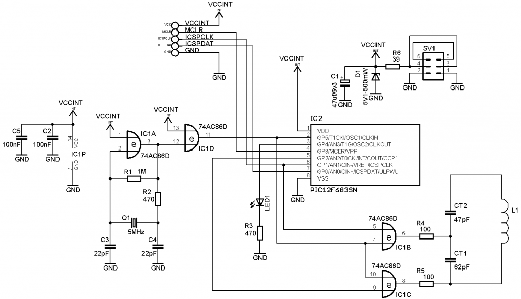
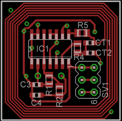
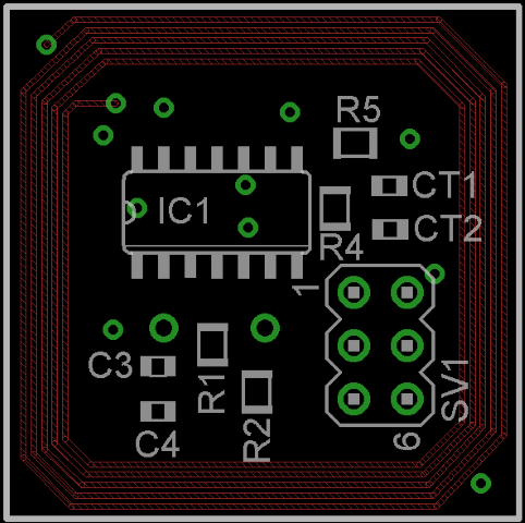
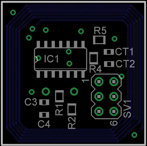
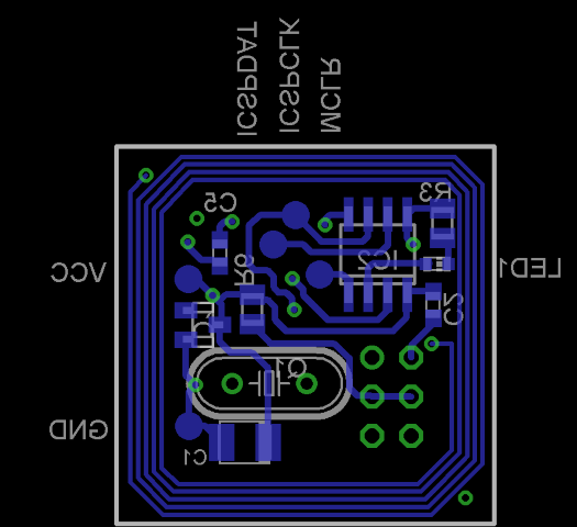
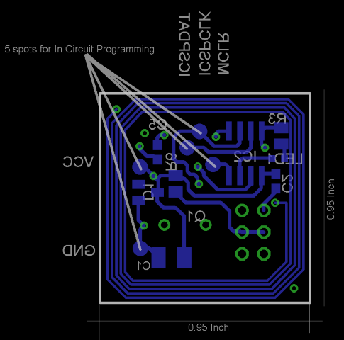
In the original transponder you have used so far is a DIP casing for the PIC-controller. It is inserted in a socket. I think it is for offroad 1/8 scale and 1/5 scale not stable enough. The IC might become loose in the sockets. For that reason I used in this design surface-mounted components for all of the components. There is a downside, the PIC controller cannot be programmed in a socket unless someone does that prior to soldering it into the PCBA. That's why used the in-circuit programming capabillities for the PIC. In the internet are various simple designs available how to programm the HEX-file into the PIC, even when in circuit programming is needed. I include the schematics in the below links. To follow up your idea to have the decoder in series to one of the receiver channels, I have the 2x3-positions to solder the incomming servo and outgoing servo cable. The transponder is supplied from the receiver battery, the servo-control signal is left untouched. I left the #ID program selector out. I think once a specific transponder ID is programmed, there is no need. Unless ofcoarse one wants to drive several cars under the same ID. The below pictures show the scematics I used to draw the PCB. Also included are the pictures of the 4 PCB layers, and to complete, also the in-circuit programming spots at the bottom_side of the PCBA are shown together with PCBA dimensions.
Schematics_picture
Layer_2
Layer_3
Bottom_layer
Info_picture
Hope the pictures will be visible as I might still have not posted enough to have these rights, let's see.
Hmmm...this message comes again: You are only allowed to post URLs to other sites after you have made a certain number of posts. You have not reached that limit yet. I need some help...(Howard possibly)
kind regards, Gerrie (PA3EXV)
I Still follow the work that is done here, as well as in the decoder threat. This week I found some time to draw a 4-layered PCBA for the transponder which I wanted to share to you.
In the original transponder you have used so far is a DIP casing for the PIC-controller. It is inserted in a socket. I think it is for offroad 1/8 scale and 1/5 scale not stable enough. The IC might become loose in the sockets. For that reason I used in this design surface-mounted components for all of the components. There is a downside, the PIC controller cannot be programmed in a socket unless someone does that prior to soldering it into the PCBA. That's why used the in-circuit programming capabillities for the PIC. In the internet are various simple designs available how to programm the HEX-file into the PIC, even when in circuit programming is needed. I include the schematics in the below links. To follow up your idea to have the decoder in series to one of the receiver channels, I have the 2x3-positions to solder the incomming servo and outgoing servo cable. The transponder is supplied from the receiver battery, the servo-control signal is left untouched. I left the #ID program selector out. I think once a specific transponder ID is programmed, there is no need. Unless ofcoarse one wants to drive several cars under the same ID. The below pictures show the scematics I used to draw the PCB. Also included are the pictures of the 4 PCB layers, and to complete, also the in-circuit programming spots at the bottom_side of the PCBA are shown together with PCBA dimensions.
Schematics_picture
Layer_2
Layer_3
Bottom_layer
Info_picture
Hope the pictures will be visible as I might still have not posted enough to have these rights, let's see.
Hmmm...this message comes again: You are only allowed to post URLs to other sites after you have made a certain number of posts. You have not reached that limit yet.
 I need some help...(Howard possibly)
kind regards, Gerrie (PA3EXV)
#128
Tech Adept
The limit is 10 posts, it's soon, you can paste the links, and add an char somewhere like this: h_ttp, we'll do the rest!
#130
Tech Initiate
perfect PA3EXV, do you make some PCB with 4 layers ?
I am interested to have some PCB !
I am interested to have some PCB !
#131
Tech Adept
Nicely done, PA3EXV.
#132
I have created some new special code for the transponders to facilitate club use. These programs will show up as ID numbers 1 through 10, and will be usable only on the Cano decoder. Hopefully that will help keep them from disappearing!
This info has also been posted in the Decoder thread.
This info has also been posted in the Decoder thread.
#133
CANO TRANSPONDER SPECIFICATIONS
I recently created a post in the decoder thread containing as much pertinent information on it as possible, so that readers don't need to go sifting through the thread. Let's do the same thing for the transponders right here! I'll try to keep this updated as necessary.
LEGALESE: All information presented on this thread is free for use for personal, non-commercial purposes. The software is copyrighted, and cannot be reproduced. Contact me for licensing arrangements if you wish to produce and market the transponders.
AVAILABILITY: The Cano transponders are not available assembled. They must be constructed. I offer programmed microprocessors; send me a private message for pricing. Proceeds from these parts will help offset my development costs.
SIZE: PC board measures 1.25" square.
WEIGHT: approximately 11 g
POWER REQUIREMENTS: 5 VDC minimum, 7.2 VDC maximum
DECODER COMPATIBILITY: "Cloned" ID numbers have been successfully tested on AMB RC2, AMB RC3, and Cano decoders. None are compatible with the AMB RC4. "Club" ID numbers function only on the Cano decoder.
ID NUMBERS: I have so far "cloned" about 30 numbers from MRT and AMB transponders. Each transponder contains one ID number. I have also created special programs for "club" or handout use. These programs contain ID numbers that function on the Cano decoder only. (Cano decoder specs are here: http://www.rctech.net/forum/12222187-post251.html)
DOCUMENTATION: The following files are available: the schematic in TinyCAD freeware format; the PC layout in FreePCB freeware format; and the Bill Of Materials (BOM) in Excel format. Send me a PM containing your email address if you would like me to forward these files to you.
CURRENT REVISIONS:
Schematic: Transponder Rev 3 6_11_13.dsn
PC Board: PT_R2 6_2_13.fpc (tested), PT_R3 6_11_13.fpc (untested)
BOM: PT BOM 6_11_13.xls
Last edited by howardcano; 07-21-2013 at 03:15 AM. Reason: Added current revisions. Added link for decoder.
#134
Tech Rookie
I've got a non working AMB RC3 personnal transponder that have the epoxy removed.
The IC chip is a SOIC-8 format having this pinout :
8 : VCC
4 : GND
3 : XTAL
2 : XTAL
The IC chip is a SOIC-8 format having this pinout :
8 : VCC
4 : GND
3 : XTAL
2 : XTAL
Last edited by Ptitoine; 06-19-2013 at 12:27 PM.


 2Likes
