


 16Likes
The Homebuilt Dynamometer (Dyno)Thread!!!
 12-26-2015 | 05:46 AM
#61
Scotty we need More power!!!!!! Crazy to think you need to use 220V to simulate a Lipo Battery.
Personally I prefer using the Lipo as the power source since that is what we use on track, voltage droop and all. When I create a model in RC3 I include the effect of battery internal resistance, wiring and ESC on resistance when creating the model. That way once the model is created I can just change the battery Internal resistance to zero and see the effect. The attached graphs provide a comparison between a typical Lipo pack with a total internal resistance of 20mOhm to an ideal voltage source with zero internal resistance hence zero voltage droop. Static voltage for both is 8V. The performance difference is huge in the lower RPM range and becomes progressively less as the motor current drops.
The thing that would concern me with the power supply is the initial current draw. It will be significantly higher than with a Lipo so it will certainly put more stress on the ESC. As you can see in this example of a 13.5T motor the initial draw goes from 150 to 250 amps. While it will be a short duration I would be cautious so you don't let the magic smoke out.
 12-26-2015 | 06:00 AM
#62
I'm sure power supplies exist that will do what I want and still operate from 120V, but (as usual) I bought the cheapest one, which happens to need 220V.
By the way, can your program accept data from a flywheel dyno-- specifically, time to each successive revolution? I'm now busy writing code to send this data to a serial port. While I can process the data in a LibreOffice spreadsheet, it looks like your program has a bunch of useful features that may not be available in a spreadsheet.
Last edited by howardcano; 12-26-2015 at 06:18 AM.
12-26-2015 | 06:14 AM
#63
One thing to note is the torque output of a brushless motor is not linear particularly at higher timing settings... If you look at the Silver Can graph below you can see the torque output is reasonably linear. Then look at the Orion Motor and you can see as the motor timing is increased the Torque output becomes much more non-linear.
12-26-2015 | 07:37 AM
#64
The torque and power curves for the Orion look pretty gnarly above 15000 RPM, so I wouldn't draw any conclusions from the data. It definitely looks like the MD2 isn't nearly accurate enough up there. And the flat top on the power curve for file1 says it isn't accurate enough at lower speeds, either. Or are these artifacts from other processing of the data?
I am still planning to get some larger flywheels made which will increase the number of samples at lower RPM and should help improve the accuracy. I look forward to seeing your results with the high sample rate. Should make for some interesting comparisons. If you share some data with me I'll process it through RC3 for you to compare with your torque and power calcs.
Are you measuring RPM directly off the motor terminals or using an external encoder or hall effect sensor?
12-26-2015 | 08:35 AM
#65
I'm taking data from one of the motor's internal Hall sensors. I'm hoping they will be accurate enough, but they are awfully close to those coils, so there may be some skew depending on current draw.
12-30-2015 | 04:49 PM
#66
Here's a status update for you kids!
I finished a first pass at the code for the data acquisition module, to measure the time to each successive motor rotation on spool-up. The module uses a PIC12F683, the same processor as I used for my transponders. It runs on a 20MHz crystal, so it does 5MIPS, and the internal timer is also clocked at 5MHz, giving it 0.2us resolution. That should be plenty! The code is arranged to capture the timer value for 16 consecutive sensor signal falling edges after the initial edge, convert the times to decimal, and spit them out on a serial port (done in software, since this processor doesn't have a UART). The data can then be processed on a spreadsheet (I'm using LibreOffice).
I initially tested the timing jitter using my "good" Siglent digital signal generator. The jitter was acceptable when sampling a 1kHz square wave, but when I went down in frequency-- giving longer periods to time-- the jitter increased. I checked the code and could see no reason for this, so I decided to swap out the signal generator with my old Madell analog generator. The jitter was much improved! I'll attribute this to the digital signal generator using a wavetable, with the pointer into the wave table not having enough resolution.
For further testing, I created a simple crystal-controlled 1Hz timebase generator, and the jitter is very good: the deviation is one count (0.2us).
Here is the data for the different signal sources:

And here's a look at the 1Hz timebase generator (for which I temporarily borrowed my servo driver case and circuit) on the left, and the data acquisition module on the right. There's not much to either one!

I finished a first pass at the code for the data acquisition module, to measure the time to each successive motor rotation on spool-up. The module uses a PIC12F683, the same processor as I used for my transponders. It runs on a 20MHz crystal, so it does 5MIPS, and the internal timer is also clocked at 5MHz, giving it 0.2us resolution. That should be plenty! The code is arranged to capture the timer value for 16 consecutive sensor signal falling edges after the initial edge, convert the times to decimal, and spit them out on a serial port (done in software, since this processor doesn't have a UART). The data can then be processed on a spreadsheet (I'm using LibreOffice).
I initially tested the timing jitter using my "good" Siglent digital signal generator. The jitter was acceptable when sampling a 1kHz square wave, but when I went down in frequency-- giving longer periods to time-- the jitter increased. I checked the code and could see no reason for this, so I decided to swap out the signal generator with my old Madell analog generator. The jitter was much improved! I'll attribute this to the digital signal generator using a wavetable, with the pointer into the wave table not having enough resolution.
For further testing, I created a simple crystal-controlled 1Hz timebase generator, and the jitter is very good: the deviation is one count (0.2us).
Here is the data for the different signal sources:
And here's a look at the 1Hz timebase generator (for which I temporarily borrowed my servo driver case and circuit) on the left, and the data acquisition module on the right. There's not much to either one!
12-31-2015 | 09:59 AM
#67
I did a few runs with the data acquisition module on a geared flywheel, and an ungeared flywheel (from my old Robotronics dyno). It appears that my fears of the gear lash affecting the data is well-founded; as you can see below, four runs on the geared flywheel resulted in quite a bit of noise in the power curves:

In contrast, the curves below, for the ungeared flywheel, are much cleaner. There is a chance that at least some of this is due to the lower MOI of this flywheel, so I'll need to check again with a "beefier" flywheel.

In contrast, the curves below, for the ungeared flywheel, are much cleaner. There is a chance that at least some of this is due to the lower MOI of this flywheel, so I'll need to check again with a "beefier" flywheel.
12-31-2015 | 01:46 PM
#69
The Arduino boards already have a USB port on board, which I assume can be used to dump data to a PC (after it is used to program the board). That would eliminate the need for an RS232-to-USB cable.
12-31-2015 | 01:51 PM
#70
Tech Lord

Joined: Aug 2007
Posts: 14,051
From: Holland
My telemetry system is based on an old datalogger and yes, people are telling me I could program it to make it work with the software of my telemetry system. Sadly I am no hero with an Arduino....
But looking arround there is something like an Arduino scope, it is an 6 channel oscilloscope
http://kll.engineering-news.org/kllf...p?article_id=8
But looking arround there is something like an Arduino scope, it is an 6 channel oscilloscope
http://kll.engineering-news.org/kllf...p?article_id=8
01-21-2016 | 08:06 AM
#71
Now that we are through the holidays, it's time for another status report!
I think I have found a suitable flywheel. It is a Gates V-pulley, #37360. It has an O.D of 2.75", and a width of about 0.62", with a 1/2" bore, no keyway, and a single set screw to lock it to the shaft. The V-pulley shape is not quite optimal, since mass is removed and surface area added near the edge, where velocity is highest. It is, however, cheap-- $9 shipped!-- and has good availability.
I also purchased a selection of shaft couplers and adapters to connect the flywheel to the 1/8" motor shaft. Unfortunately, all of them had substantial runout and/or wobble. My highest hopes were for the Master Airscrew prop adapter, #MA3200, which has a pretty accurate O.D. that matches the pulley bore (though this is not guaranteed the same on all adapters), but it also had a bunch of wobble. While runout and wobble between the 1/8" bore and the 1/2" diameter around it is not important in its intended use, the excessive runout and wobble is also present at the surfaces where the prop attaches, and that is disappointing. It's probably time to talk to my buddy that owns a CNC lathe!
Since I still wanted to take some data with the direct drive flywheel, but don't yet have the heavier one ready, I went back and did some runs with the one from my Robitronics dyno, but with resistance added in series with each motor terminal to reduce the motor power and increase the spool-up time. About 45 milliohms extra on each terminal of the 21.5T motor moved the calculated power peak to around the eighth revolution. Four successive runs showed about 0.36% total variation in the calculated power, so I'm definitely on the right track to getting the repeatability results I want!
01-31-2016 | 03:12 AM
#72
After some thought, I have realized I can get more data from a single run by monitoring all three Hall sensors in the motor, and use this to enhance the repeatability (i.e., reduce the noise levels) of the data. While the alignment of the sensors in the motor is not nearly accurate enough to get useful information from the time between their signals, we can still process the data from each sensor independently (as if we had done three separate dyno runs to get it) and then average the results as a final step. (There may also be other information available from the sensors-- for instance, is the data from one consistently "noisier" than from the others?-- but that remains to be seen.)
To this end, I have ordered some PIC16F1825 microprocessors. The PIC16F1825 has enough pins to bring in the three sensor signals, enough memory to store the extra data, and dedicated capture/compare/PWM hardware timing "modules" for up to four signals. Since there are only three motor Hall sensors to monitor, the fourth module will generate the signal to control the ESC during a dyno run, eliminating the need for a servo driver or transmitter/receiver.
The PIC16F1825 is from a newer family of designs, so I also needed to order a new programmer for it. Of course, the data acquisition software needs to be changed to accommodate both the new microprocessor and the new functionality, and I have finished a first pass at this.
I have also changed the LibreOffice spreadsheet to accept the data from all three sensors.
News on the flywheel: I have been communicating with a machinist about machining a hub for the Gates V-pulley, or perhaps even creating the entire flywheel as a single piece. We'll try to keep the cost reasonable for those of you who want to make your own dyno!
03-08-2016 | 02:43 PM
#73
It's time for another update!
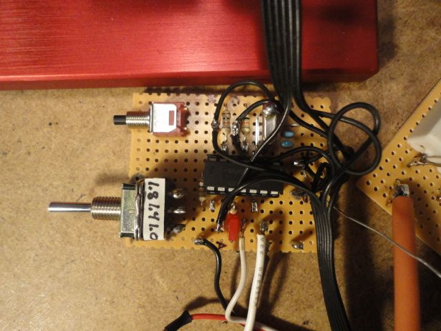
Here is a photo of the data acquisition board with the new microprocessor. It runs at 4MHz, which gives a resolution of 1us on the sensor timing. The program now gathers data from all the sensors, and for 80 motor revolutions to give more information at high RPM, which makes it easier to estmate the maximum RPM via extrapolation. The toggle switch selects the correct pulse width when calibrating the ESC, and the push button starts a dyno run.
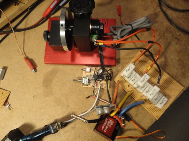
Here is the system connected to the motor and ESC. The resistor bank makes the motor spool up slower since I'm still using the Robitronics flywheel. Unfortunately, the heavier flywheel is still in limbo. If anyone wants to machine one, let me know!
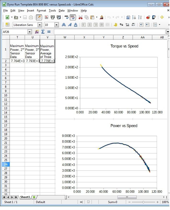
Here is a screen capture of the updated spreadsheet. In addition to expanding it to accept data for 80 revolutions from the three sensors, I also re-arranged the graphs to get velocity on the X axis. As you can see, the torque and power curves are quite smooth, with the data for the three sensors very nearly superimposed on each other. The peak power occurs at almost exactly 1/2 of the free-running speed, which is reassuring. At the moment, none of the values are scaled to any particular units.
Here is a photo of the data acquisition board with the new microprocessor. It runs at 4MHz, which gives a resolution of 1us on the sensor timing. The program now gathers data from all the sensors, and for 80 motor revolutions to give more information at high RPM, which makes it easier to estmate the maximum RPM via extrapolation. The toggle switch selects the correct pulse width when calibrating the ESC, and the push button starts a dyno run.
Here is the system connected to the motor and ESC. The resistor bank makes the motor spool up slower since I'm still using the Robitronics flywheel. Unfortunately, the heavier flywheel is still in limbo.
If anyone wants to machine one, let me know!Here is a screen capture of the updated spreadsheet. In addition to expanding it to accept data for 80 revolutions from the three sensors, I also re-arranged the graphs to get velocity on the X axis. As you can see, the torque and power curves are quite smooth, with the data for the three sensors very nearly superimposed on each other. The peak power occurs at almost exactly 1/2 of the free-running speed, which is reassuring. At the moment, none of the values are scaled to any particular units.
Last edited by howardcano; 03-08-2016 at 02:56 PM.
08-17-2016 | 02:25 PM
#74
Tech Rookie
Joined: Aug 2016
Posts: 4
From: Modena, Italy
Hi all
here is my experimental stand-alone dyno based on a single arduino mini-pro board running at 16Mhz.


The photos are a test with an old rc car brushed motor.
The aluminium flywheel, with six optical sensing holes, is of about 50e-6 kgm^2.
The current/efficiency graph is yet missing; work in progress.
here is my experimental stand-alone dyno based on a single arduino mini-pro board running at 16Mhz.
The photos are a test with an old rc car brushed motor.
The aluminium flywheel, with six optical sensing holes, is of about 50e-6 kgm^2.
The current/efficiency graph is yet missing; work in progress.

