


 16Likes
The Homebuilt Dynamometer (Dyno)Thread!!!
 09-09-2016 | 03:23 PM
#76
Tech Addict
Joined: Sep 2014
Posts: 509
From: London, United Kingdom
New commercial dyno on the block, looks quite nice!
https://www.miniprousa.com/collectio...540-motor-dyno
https://www.miniprousa.com/collectio...540-motor-dyno
 09-09-2016 | 04:04 PM
#77
New commercial dyno on the block, looks quite nice!
https://www.miniprousa.com/collectio...540-motor-dyno
https://www.miniprousa.com/collectio...540-motor-dyno
02-01-2017 | 02:56 AM
#78
Tech Adept
iTrader: (-1)
Joined: Dec 2014
Posts: 186
Howard,
Have you thought about using a load cell / strain gauge in conjunction with a flywheel to directly measure torque? This way you dont need a high accuracy to calculate the flywheels second moment of inertia and also no need to accurately time its acceleration.
All you'd need is a load cell (lever mounted off motor housing) and a hall effect sensor on the flywheel to obtain rpm. With a simple 2 channel logger, you can easily obtain torque, rpm = power.
Maybe use an extra 2 channels to log amperage and voltage to obtain electric power, so you can use that to calculate mechanical efficiency at any given rpm.

http://www.ebay.com.au/itm/100g-Elec...kAAOSwImRYXQNl
http://www.ebay.com.au/itm/YZC-191-W...3D301706904557
http://www.ebay.com.au/itm/2-2-lbs-1...ro_PfdDOXo7Atw
Have you thought about using a load cell / strain gauge in conjunction with a flywheel to directly measure torque? This way you dont need a high accuracy to calculate the flywheels second moment of inertia and also no need to accurately time its acceleration.
All you'd need is a load cell (lever mounted off motor housing) and a hall effect sensor on the flywheel to obtain rpm. With a simple 2 channel logger, you can easily obtain torque, rpm = power.
Maybe use an extra 2 channels to log amperage and voltage to obtain electric power, so you can use that to calculate mechanical efficiency at any given rpm.
http://www.ebay.com.au/itm/100g-Elec...kAAOSwImRYXQNl
http://www.ebay.com.au/itm/YZC-191-W...3D301706904557
http://www.ebay.com.au/itm/2-2-lbs-1...ro_PfdDOXo7Atw
02-01-2017 | 08:51 AM
#79

Howard,
Have you thought about using a load cell / strain gauge in conjunction with a flywheel to directly measure torque? This way you dont need a high accuracy to calculate the flywheels second moment of inertia and also no need to accurately time its acceleration.
All you'd need is a load cell (lever mounted off motor housing) and a hall effect sensor on the flywheel to obtain rpm. With a simple 2 channel logger, you can easily obtain torque, rpm = power.
Maybe use an extra 2 channels to log amperage and voltage to obtain electric power, so you can use that to calculate mechanical efficiency at any given rpm.
http://www.ebay.com.au/itm/100g-Elec...kAAOSwImRYXQNl
http://www.ebay.com.au/itm/YZC-191-W...3D301706904557
http://www.ebay.com.au/itm/2-2-lbs-1...ro_PfdDOXo7Atw
Accurate timing is much easier than any other measurement, and I've already made the data acquisition system to do it, as you can see from my previous posts.
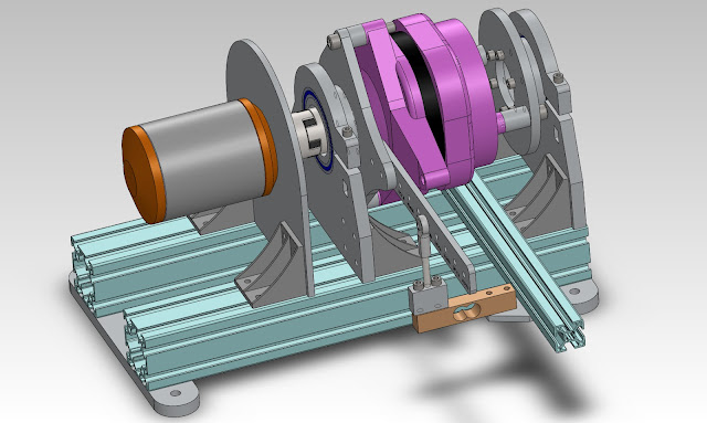
On another note, I've recently obtained a flywheel of the correct inertia, thanks to Benjamin Fenton and a friend, so the next order of business is to make a proper support for the motor/flywheel combo.
02-02-2017 | 01:41 AM
#80
Tech Adept
iTrader: (-1)
Joined: Dec 2014
Posts: 186
Its not complex... and it is not changing your flywheel design... it just adds to it. All it does is allow you to measure torque directly as apposed to deriving it from acceleration... That will not be accurate. All rotating mass (including armature) will affect your result. A strain gauge is by far more accurate.
Also I dont think getting precision rpms is that simple... especially when you consider its high speed (30k+ rpms) and achieve peak power in less than a second.
I find it pretty hard to believe that motor dynos cant be bought any more. Surely there is something available out there (besides the ripoff mc crappy racing)
02-02-2017 | 03:05 AM
#81
Tech Addict
Joined: Sep 2014
Posts: 509
From: London, United Kingdom
Its not complex... and it is not changing your flywheel design... it just adds to it. All it does is allow you to measure torque directly as apposed to deriving it from acceleration... That will not be accurate. All rotating mass (including armature) will affect your result. A strain gauge is by far more accurate.
02-02-2017 | 03:44 AM
#82
Another big problem with the strain gauge is its frequency response. It needs to be free of mechanical resonances (which is problematic, since it is a spring!), and the bridge amplifier must have sufficient frequency response to make negligible the settling time to a value within the required error band.
Given all of the above, I'd say the strain gauge will likely be less accurate (and certainly less repeatable) than calculating torque from acceleration. Calibrating the calculated result to any given units might be more bothersome. But, as Mr. Phaneuf stated, that step isn't necessary to tune a motor, or compare motors.
It seems simple to me, since I have already done it. There is virtually no hardware required: the motor's existing Hall sensors, and one counter inside a microprocessor. Every other way of doing it seems more complicated.
Last edited by howardcano; 02-02-2017 at 04:11 AM.
02-02-2017 | 03:51 AM
#83
Tech Adept
iTrader: (-1)
Joined: Dec 2014
Posts: 186
Yeah, I saw that link before.
The good thing about the belt drive is that since it has some elasticity, it will help to filter out any vibrations or intermittent accelerations... or perhaps one would want to see that for diagnosis purposes.
Though I'm not really liking their design. Especially the motor mount. And for the price... its pretty impractical and unrealistic.
02-02-2017 | 04:06 AM
#84
Tech Adept
iTrader: (-1)
Joined: Dec 2014
Posts: 186
I was actually going to use my (automotive) engine data logger to capture the data points.
With a big enough flywheel, I dont think discrepancies in data latencies would be of much concern. My 2 variables would be torque and rpm. Yours would be rpm and elapsed time. I think your issue may be with your data loggers resolution when taking so many data points in such a short period of time.
However you have a point with mechanical resonance... but thats still going to be an issue regardless. You can only dampen that with a larger flywheel and an external damper on the strain gauge.
Personally speaking, I just wanted to obverve torque directly, not calculated indirectly.
The strain gauge method is still very doable. Its pretty much industry standard for automotive engine dynos (w/ water brake)
The other alternative to a strain gauge to avoid its spring like harmonics is to use a different kind of load cell instead. i.e. compression instead of bending
Last edited by ModeratedUser30082018; 02-02-2017 at 04:23 AM.
 02-02-2017 | 04:17 AM
#86
I'm guessing that your automotive logger operates as a sampled system, as most loggers do. Then the concern is: What is the sample rate? If the sample rate is 100Hz, then the time resolution is 10000us. That's useless for a flywheel dyno.
Last edited by howardcano; 02-02-2017 at 04:31 AM.
02-02-2017 | 04:24 AM
#87
What kind of load cell are you referring to? They are all essentially springs with means to measure deflection, or active force-balancing designs (e.g. electromagnetic "voice-coil" types) with means to measure drive current or voltage.
02-02-2017 | 05:03 AM
#88
Tech Adept
iTrader: (-1)
Joined: Dec 2014
Posts: 186
http://au.omega.com/subsection/minia...oad-cells.html
Not all strain gauges rely on measuring deflection. Some use variances in the dielectric properties of the material when placed under mechanical stress. Since I'm only a mechanical engineer, not electrical, sensor operation is not really my expertise.
you could also utilise rubber joints to absorb some more vibration too
As I said before, the sample rate is somewhat irrelevant with a large enough flywheel and directly measured torque + rpm
02-02-2017 | 07:06 AM
#89
Again, correct, although once the flywheel gets to a certain size, it would be more expedient to just make a brake dyno. Keeping the flywheel as small as possible reduces the problem of motor heating, which is always a problem with our RC motors on brake dynos.
02-02-2017 | 05:12 PM
#90
Tech Adept
iTrader: (-1)
Joined: Dec 2014
Posts: 186
A brake dyno in theory works... however 2 machines will never be calibrated the same. The levels of friction vary to much, and not to mention heating of the friction material causes more inconsistencies. It worked back in the day without computers. Now days a water brake is used instead... however I don't think that could be scaled down to our application. It would be hella cool though 
Regarding motor temperatures, I see it as a good point. As it will give you a better understanding of how the motor will behave under heavy load. You wont be making pull after pull as that would be unnecessary. I believe there is enough thermal mass in the motor, wires, heat sinks and a solid metal frame to make this negligible.
Regarding motor temperatures, I see it as a good point. As it will give you a better understanding of how the motor will behave under heavy load. You wont be making pull after pull as that would be unnecessary. I believe there is enough thermal mass in the motor, wires, heat sinks and a solid metal frame to make this negligible.