


 8Likes
Lap Timing Decoder


 04-26-2013 | 06:01 AM
#199
Tech Initiate
Joined: Apr 2013
Posts: 46
my problem :
1st picture
h_ttp://hostingpics.net/viewer.php?id=887040scope1.png
yellow : between R9 & R10 of the phasqe detector input amplifier
green : pin 4 of the 74HC04
first picture, the 74HC04 is not powered.
2nd picture, the 74HC04 is powered with filtrage capacitor (100nF)
2nd picture
h_ttp://hostingpics.net/viewer.php?id=953389scope4.png
thanks.
04-26-2013 | 07:50 AM
#200
my problem :
1st picture
h_ttp://hostingpics.net/viewer.php?id=887040scope1.png
yellow : between R9 & R10 of the phasqe detector input amplifier
green : pin 4 of the 74HC04
first picture, the 74HC04 is not powered.
2nd picture, the 74HC04 is powered with filtrage capacitor (100nF)
2nd picture
h_ttp://hostingpics.net/viewer.php?id=953389scope4.png
thanks.
1st picture
h_ttp://hostingpics.net/viewer.php?id=887040scope1.png
yellow : between R9 & R10 of the phasqe detector input amplifier
green : pin 4 of the 74HC04
first picture, the 74HC04 is not powered.
2nd picture, the 74HC04 is powered with filtrage capacitor (100nF)
2nd picture
h_ttp://hostingpics.net/viewer.php?id=953389scope4.png
thanks.
The second scope shot shows the analog signal converted to CMOS digital levels. This is what the Phase Detector Input Amplifier does.
04-26-2013 | 01:27 PM
#201
The first pass at software for calculating the transponder crossing times inside the decoder is done! I found the code to be fairly challenging given the small amount of RAM and processing power, but it certainly does eliminate the timing bottleneck of sending every transponder message to the PC; now the decoder sends only one message per transponder after it crosses the timing loop.
So now we are ready for all of you software enthusiasts to write your own scoring software on the PC. Several of our readers have already expressed an interest in doing so.
The communication from decoder to PC is similar to what I have already described in this thread, so please forgive me if some of this seems repetitious:
The decoder sends a message to the PC every time each “verified” transponder has passed through the loop. (The decoder verifies each transponder as it passes individually through the loop; the criteria for verification are three consecutive identical messages received from the transponder. No input from the scoring PC is required for this to occur.)
The decoder messages are logic-level asynchronous serial “RS232” at 115200 baud, 8 data bits, no parity, 1 stop bit, and no flow control. This may be converted to USB using an adapter cable. (I’m using a Sabrent SBT-USC6M USB to Serial Adapter Cable from Walmart.) Each message consists of 16 bytes: The first 6 bytes are ASCII hexadecimal characters representing the first 24 bits of each transponder transmission after the preamble, which we will use for the transponder ID. The next 8 ASCII hexadecimal characters are the timestamp, MSB first, in increments of 1/4 millisecond. (Zero time is when the decoder was powered-up.) The string is terminated with a carriage return and line feed. Here is a typical example:
CDFD4C00FFB6DA
And here is a message for the same transponder ID, but with the timestamp incremented by 10 seconds (a typical lap time):
CDFD4C0100531A
Here’s a synopsis of what the PC must do:
Before starting a race, all cars must individually cross the loop so that the decoder will recognize/verify their transponder IDs and send messages to the scoring PC. The PC then verifies that all of the correct cars are present. (This usually happens in the race “warm-up”.) Then all cars line up behind the starting loop, and the PC sounds a tone to start the race.
The PC receives messages from the decoder as each transponder crosses the loop, and stores the messages. When a second message is received for any given transponder ID, the PC examines all the timestamps it has received since the tone sounded, and determines which has the lowest value. The PC then calculates the finishing time for the race by adding the race length to this timestamp.
As each new message for any given transponder is received, the PC subtracts the current and previous timestamps for that transponder to get the lap time. The race ends when the timestamp for each transponder exceeds the calculated finishing time for the race (or manually if some cars have dropped out of the race).
Due to the separate tasks running inside the decoder, the message for each transponder may not show up at the PC in correct chronological order, but this is immaterial since the timestamps for each transponder will be correct.
Last edited by howardcano; 05-02-2013 at 12:42 PM. Reason: Changed "as it crosses the timing loop" to "after it crosses the timing loop".
04-27-2013 | 11:43 AM
#202
Tech Initiate
Joined: Dec 2012
Posts: 48
And I have some tests http://www.youtube.com/watch?v=cEyrX...ature=youtu.be
Later I will add english subs for you
Later I will add english subs for you
05-01-2013 | 07:01 AM
#203
And I have some tests http://www.youtube.com/watch?v=cEyrX...ature=youtu.be
Later I will add english subs for you
Later I will add english subs for you
05-03-2013 | 12:21 PM
#205
I have finished a PC board layout for the decoder. The board size is currently 4.5� x 2.7�, to fit in a Radio Shack aluminum box. When finances permit, I�ll order a few prototypes.
Prototype circuit boards have gone way up in cost since the last time I ordered them. I wasn�t expecting a 4 layer board of these modest dimensions to cost $100!
I�ll also do a layout for the loop amplifier, though it is simple enough to construct on a perfboard.
I have a first pass done on the decoder Bill Of Materials (BOM), in Excel. It includes the manufacturer and distributor part numbers and pricing in small quantities. If anyone is interested, send me a PM and I can email the BOM to you.
05-05-2013 | 05:42 AM
#206
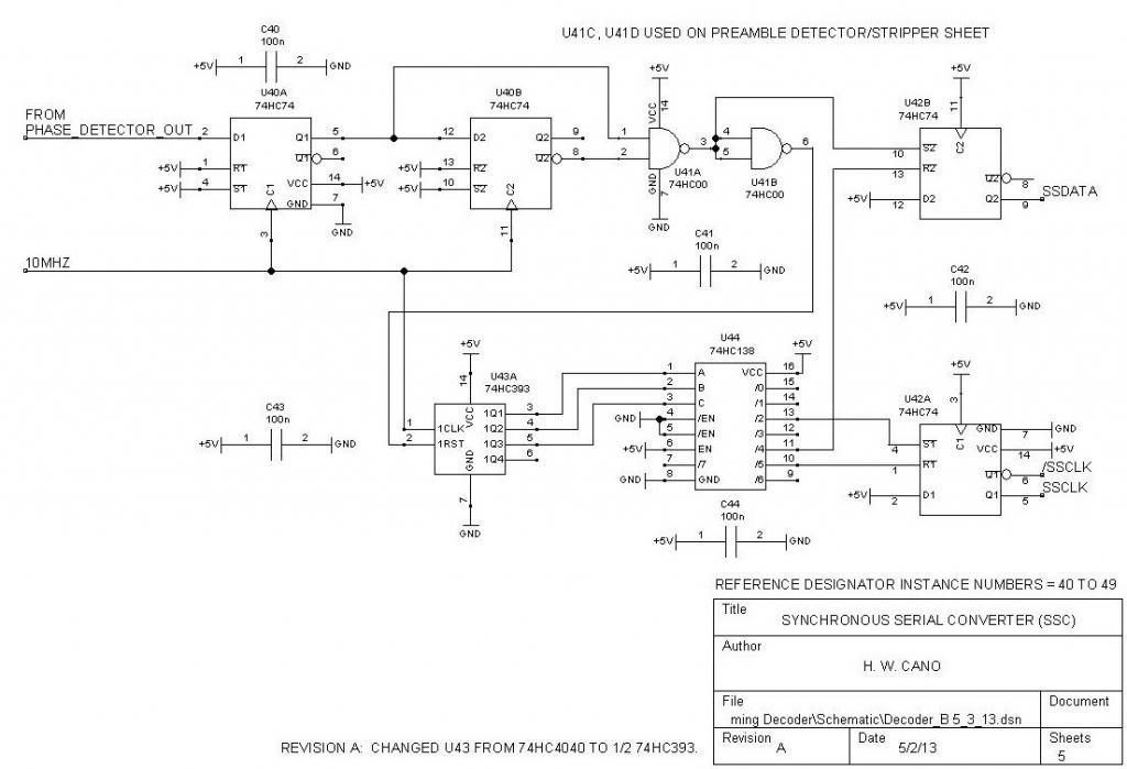
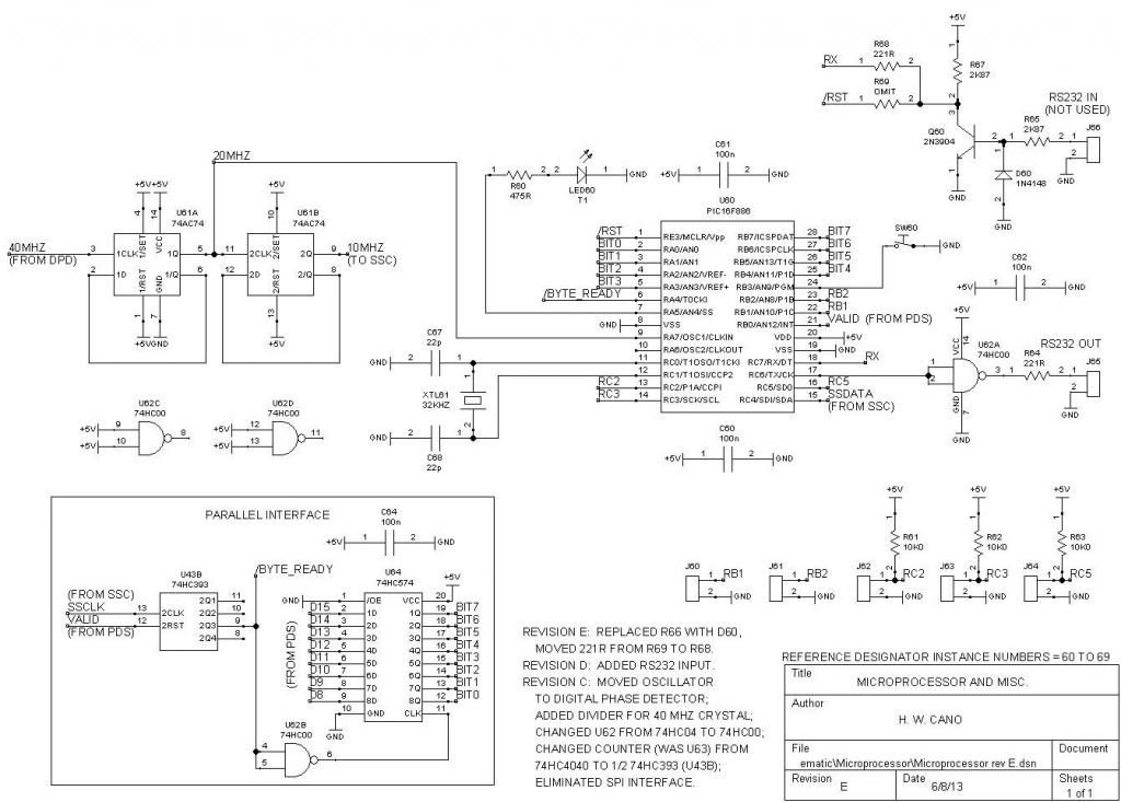
Here are the latest schematics for the decoder. There are minor changes to make the PC layout easier, but no functional changes other than the inclusion of a 5V regulator. (The current drain of the prototype is less than 100 mA, so it should be possible to omit the regulator and run the decoder from a USB port.)
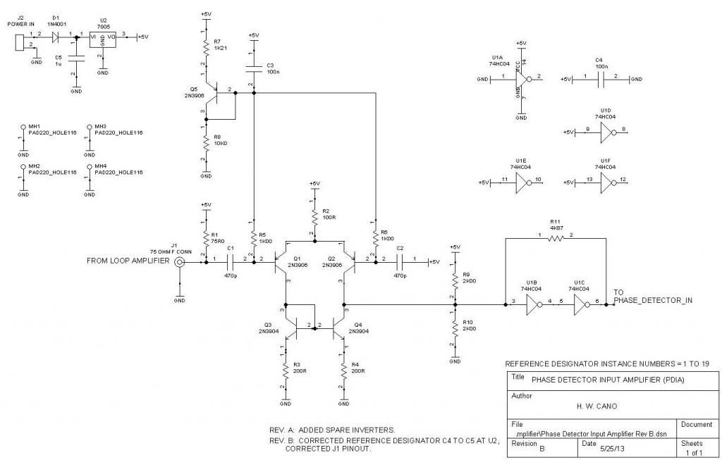


The loop amplifier is on a separate PC board, but for convenience I'll include the schematic here:

The loop amplifier is on a separate PC board, but for convenience I'll include the schematic here:
Last edited by howardcano; 09-04-2013 at 03:49 PM. Reason: Changed R66, 10K resistor, to D60, 1N4148 diode. 221R resistor at R69 moved to location R68.
05-05-2013 | 06:09 AM
#207
Several readers have contacted me regarding the program for the PIC16F886. Here�s the status:
I will be offering programmed, code-protected microprocessors for the decoder for a nominal fee, just as I did with my transponder design. Hopefully I can recoup some of the (now substantial!) money I have spent sourcing parts for this project. I will not release source code or hex files for the program. The microprocessors will be available after I have tested the PC layout and some type of PC scoring program.
I will be offering programmed, code-protected microprocessors for the decoder for a nominal fee, just as I did with my transponder design. Hopefully I can recoup some of the (now substantial!) money I have spent sourcing parts for this project. I will not release source code or hex files for the program. The microprocessors will be available after I have tested the PC layout and some type of PC scoring program.
05-05-2013 | 06:10 AM
#208
Three of the PC-scoring-software companies that I have contacted have responded, and are interested in supporting the �Cano� decoder. One company, ZRound, has already provided a test version of their software, and I have successfully run it with the decoder, in practice mode. Next I�ll try qualifying and race modes. Here�s a very big THANK YOU to ZRound for their efforts!
 )))
)))