


 24Likes
Discharge bank build?
 01-16-2019 | 06:26 PM
#1
Hello,
sorry if this has been discussed but I can’t find it in the search,
i would like to make my own discharge bank and wondering if anyone has information on this? Where to buy the products, etc...
any help is much appreciated
thank you
sorry if this has been discussed but I can’t find it in the search,
i would like to make my own discharge bank and wondering if anyone has information on this? Where to buy the products, etc...
any help is much appreciated
thank you
Last edited by kunemlavat; 01-16-2019 at 08:47 PM.
 01-16-2019 | 07:08 PM
#2
Tech Regular
iTrader: (1)
Joined: Feb 2010
Posts: 421
What amp rate are you trying to discharge at? The simplest solution is to buy 100w 1ohm resistors on eBay. Then get a heatsink to mount them to and some fans to keep the heat under control. I made a simple one just because I didn't want my charger to bear the load of having to do it. I bought a Lipo low voltage alarm that I could set to go off when I reached my desired voltage. 4 resistors I use 2 of them in parallel to discharge my 2s Lipos and 2 in series for 4s Lipos. It doesn't exactly regulate the discharge current precisely but it is within reason because the 2s Lipos are discharged at a current that is equal to twice the battery voltage and the 4s is equal to the battery voltage. The biggest thing i have to be concerned about is the amount of heat tgis set up puts out. Which is around 150 to 180 watts. If i wanted a higher discharge current I would need to add more resistors. For the 2s Lipos I would add them in parallel. For the 4s Lipos it would be a much more complicated configuration. For the 2s Lipo 1 more resistor in parallel would discharge at 3 times the battery voltage and 4 resistors would discharge at 4 times the resistance. With all that said someone is selling a nice discharger right now for $40 if you are in America that does 30 amps.
01-16-2019 | 07:25 PM
#3
Great info!
I would like to discharge around 25-30 amps. I found the 100 watt 1ohm resistors but next is the heat sink and fans. I can wire them up just need the product, also the wire connector that goes through the resistor ends and gets soldered to each resistor.
I would like to discharge around 25-30 amps. I found the 100 watt 1ohm resistors but next is the heat sink and fans. I can wire them up just need the product, also the wire connector that goes through the resistor ends and gets soldered to each resistor.
01-16-2019 | 08:51 PM
#5
Tech Regular
iTrader: (1)
Joined: Feb 2010
Posts: 421
The math behind a 2s is fairly simple. The 4s is a bit more complex because to do a 30 amp discharge with 1ohm resistors requires a combination seroes parallel circuit. OHMS law states voltage= amps X resistance. Or to rewrite it to figure out how much current you are drawing amps = voltage / resistance. The voltage somewhat varies if you are not using a icharger regenerative discharging so just use the peak voltage of the battery for the safest route. Resistance can be calculated a couple different ways the easiest way for me to explain it is by using resistors of equal value. Using this formula (1 / n ) X (value of resistor) where n is the number of resistors you put in parallel so if you use 4 resistors in parallel you get (1 / 4 ) X 1 = .25 OHMS and putting that into ohms law you would get 8.4/.25 = 33.6 amps. Watts law is power= amps X voltage you get 8.4 X 33.6 = 282 watts which is quite high. That power would be distributed across 4 resistors equally so each resistor dissipates 70.5 watts which is why I recommend 100 watt resistors for safety. The fans and the heat sinks are to help control that much heat.
01-16-2019 | 09:16 PM
#6
Tech Regular
iTrader: (1)
Joined: Feb 2010
Posts: 421
I used a couple heatsinks like https://www.ebay.ca/itm/Heat-sink-10...4n8z:rk:1:pf:0
Also use some thermal paste between the heat sinks and the resistors.
Resistors like https://www.ebay.ca/itm/25-50-100W-0...ODhA:rk:6:pf:0
You can use some scrap solid bare wire from a new house being built. Personally I just used some 12 gauge stranded wire I had lying around. It was a little trickier to solder but not to difficult. I would aim for a minimum of 14 gauge.
For fans you can use PC fans I'm trying to find some of those nice fans that are built around heatsinks.
01-16-2019 | 09:19 PM
#7
Sounds good, 👌 very detailed I have all the info for wiring now! Thank you,
The resistors I found are 100w at 1 ohm. I would like to run 5 parallel. I found copper wire to solder connect the resistors. Just trying to figure out how to mount a heat sink and fans clean and nice 👍
The resistors I found are 100w at 1 ohm. I would like to run 5 parallel. I found copper wire to solder connect the resistors. Just trying to figure out how to mount a heat sink and fans clean and nice 👍
01-17-2019 | 05:44 AM
#8
Joined: Mar 2011
Posts: 6,410
From: Austin,TX
01-17-2019 | 05:52 AM
#9
Tech Lord

Joined: Aug 2007
Posts: 14,052
From: Holland
01-17-2019 | 07:36 AM
#11
Tech Initiate
Joined: Aug 2018
Posts: 37
From the X6 Charger thread:
The Discharge+ function on the X6 charger requires a specific resistance to achieve the desired discharge rate. The X6 itself can dissipate up to 30W maximum. To extend this, we need to use external resistors with heatsinks. Assuming that we allow the X6 to dissipate 30W, and the rest will be dissipated by the resistor bank we make, we can use the following formula to calculate the minimum resistance of our bank:
Resistance minimum = (((Vmax * Id) - P) / Id^2 ) , where Vmax is the max battery voltage, Id is the discharge current, and P is the 30W dissipated from the X6.
This results in the following results for:
2S batteries:
10 Amps: 0.54 Ohms, 54 Watts
20 Amps: 0.345 Ohms, 138 Watts
30 Amps: 0.247 Ohms, 222 Watts
1S batteries:
10 Amps: 0.12 Ohms, 12 Watts
20 Amps: 0.135 Ohms, 54 Watts
30 Amps: 0.107 Ohms, 97 Watts
For the desired discharge rate, you will need a resistor bank of the correct value, and rated for the power dissipation. For 30 Amp, 2S discharge, it looks like 4 x 1 Ohm resistors in parallel, each rated for at least 60W, should work. Be sure to attach these resistors to a large heatsink, to dissipate the heat.
Cheers.
01-17-2019 | 04:13 PM
#13
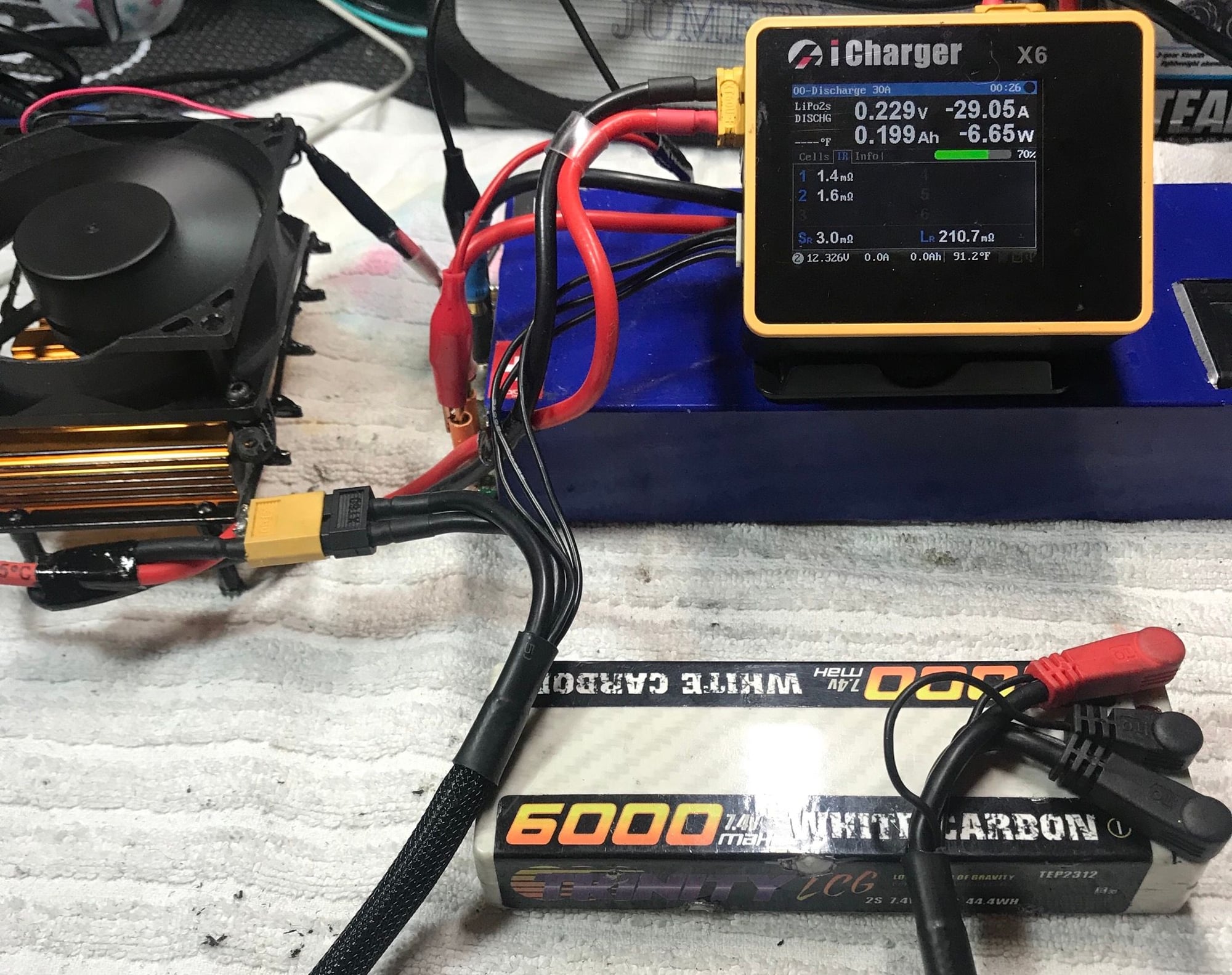
Like this nice 30amp discharge ?
 cost me less than $10 in resistors from amazon and got them the same day
 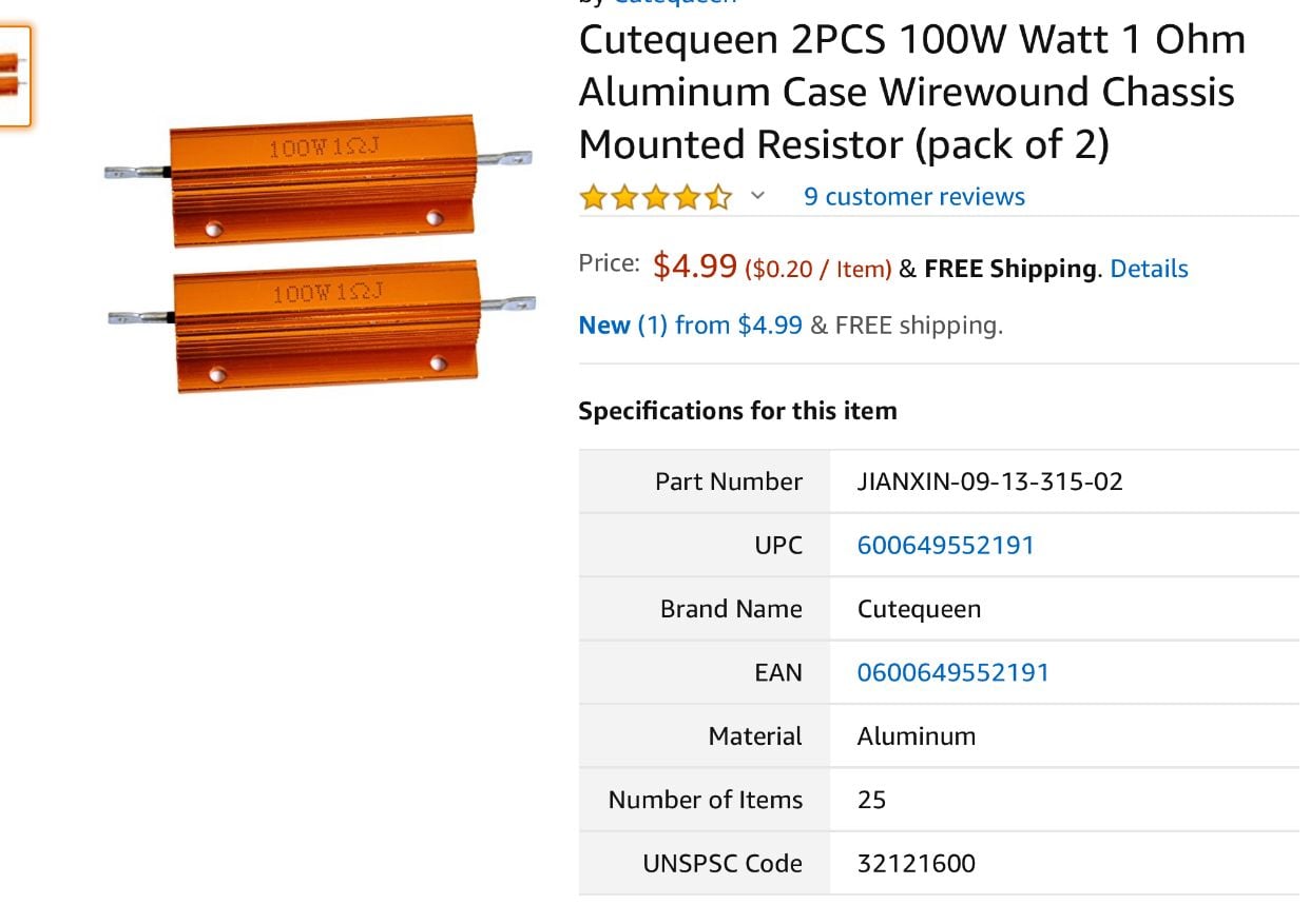 01-17-2019 | 07:22 PM
#15
Tech Initiate
Joined: Oct 2018
Posts: 22
The math behind a 2s is fairly simple. The 4s is a bit more complex because to do a 30 amp discharge with 1ohm resistors requires a combination seroes parallel circuit. OHMS law states voltage= amps X resistance. Or to rewrite it to figure out how much current you are drawing amps = voltage / resistance. The voltage somewhat varies if you are not using a icharger regenerative discharging so just use the peak voltage of the battery for the safest route. Resistance can be calculated a couple different ways the easiest way for me to explain it is by using resistors of equal value. Using this formula (1 / n ) X (value of resistor) where n is the number of resistors you put in parallel so if you use 4 resistors in parallel you get (1 / 4 ) X 1 = .25 OHMS and putting that into ohms law you would get 8.4/.25 = 33.6 amps. Watts law is power= amps X voltage you get 8.4 X 33.6 = 282 watts which is quite high. That power would be distributed across 4 resistors equally so each resistor dissipates 70.5 watts which is why I recommend 100 watt resistors for safety. The fans and the heat sinks are to help control that much heat.