


 10Likes
Building a discharger
 02-16-2018 | 03:48 PM
#1
Thread Starter
Tech Lord

Joined: Aug 2007
Posts: 14,052
From: Holland
So many topics about iChargers and high current discharge banks that made me think to give it a try. A small experimant with 10A discharge did gave some results on the internal resistance that I wanted more.
One remark: this design is only for 2S batteries but can be made for higher voltages as well.
I have no iCharger so it must be something stand alone. I have this LiPo checker/monitor
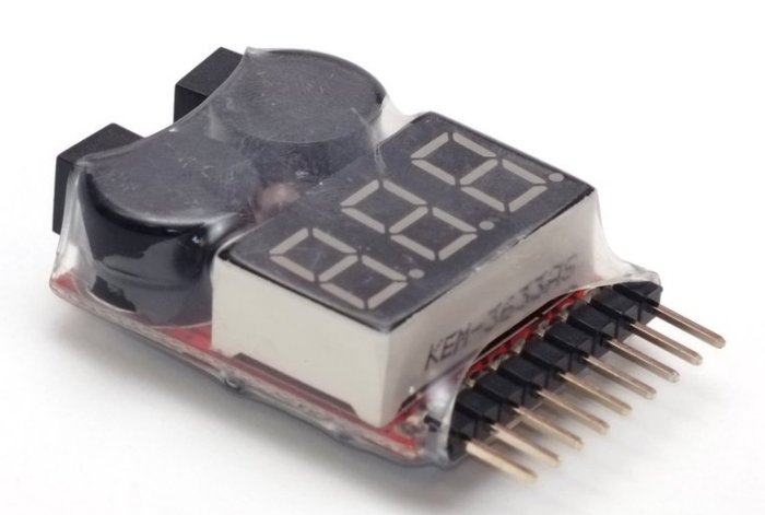
This one can be bought all over the world, it has a monitor and alarrm function. The alarm is voltage adjustable from 2.7v up to 3.8v in 0.1v steps.
After a small investigation it seems the LiPo alarm is provided by the 2S (7.4v) connection and the LED with the 2 buzzers are switched to the ground by a simple transistor. This signal will be used to stop the discharging.
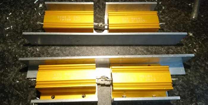
I decided to get 0.82 ohm - 100 watt resistors, I was thinking of 5 max (50A) but in a package of 6 it was cheaper to get
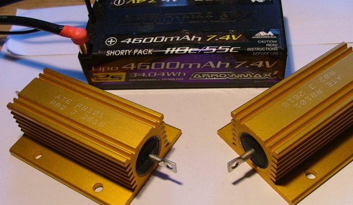
(next to a shorty LiPo)
The diagram so far
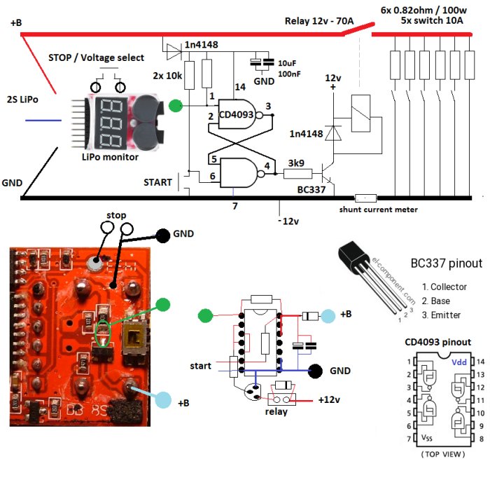
A small Set/Reset flipflop with the 2 NAND gates is the extension of the LiPo monitor. 1 push button to start and using the beep signal from the monitor to stop. The push button for the voltage select is causing a beep when pressed so it can directly used as a stop button.
Through a transistor a 12v automotive relay is powered to activate the resistor bank. The resistor bank will have 1 direct connected resistor and the other 5 are switchable, so it can be set from 10 up to 60A in 10A steps.
The shunt resistor is from a 10 dollar Ebay 100A/100v panel meter.
The relay, the panel meter and the LED lights in the 10A switches will be powered by a sepperate 12v power supply to be sure no high current will be drawn from the battery when it is stopped, only the LiPo monitor will stay powered by the battery and that is not much.
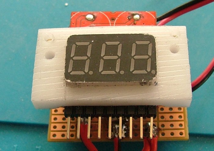
To mount the LiPo monitor as a panel meter in a case I had to remove the 2 buzzers, they will be mounted on the back side of the PCB when all wirering is done.
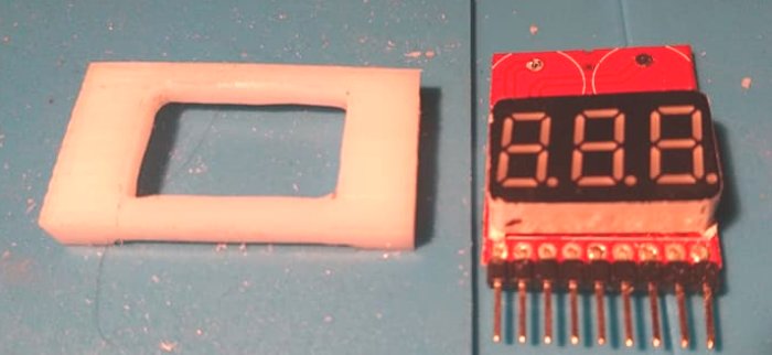
From a piece of nylon I made a tight frame arround the 3 digit display.
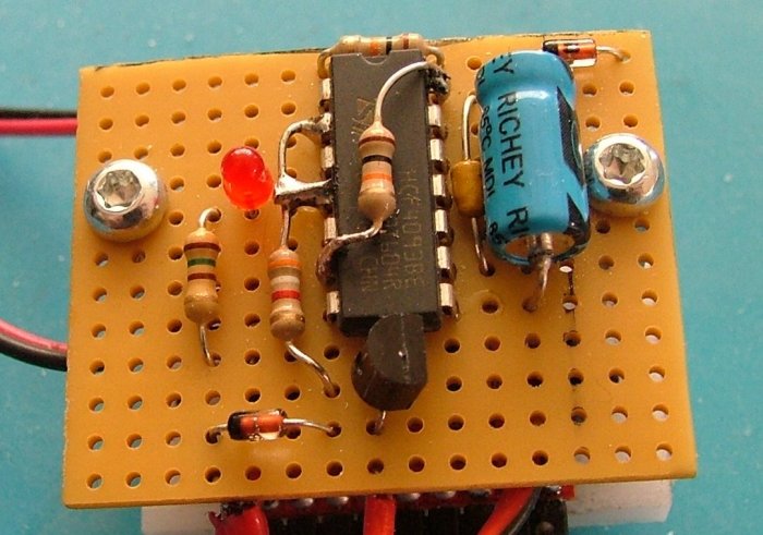
On the back with some spacers the extended electronics
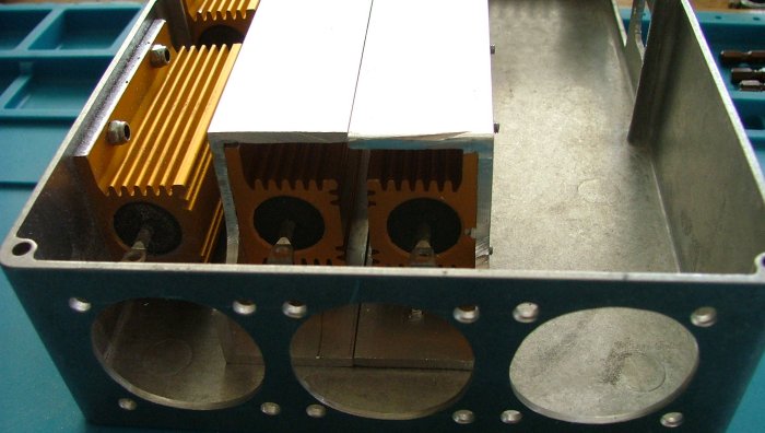
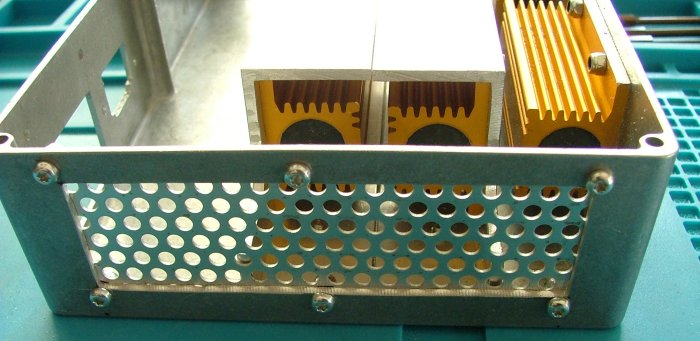
I have found an aluminium case, 2 resistors are mounted to the back and the other 4 on frames in the middle.
With on one side 3 fans will be mounted and on the other side some holed aluminium for the air intake to disipate the 500 watt max of heat.
And made some nice feets for the case:

That is so far the build, I am waiting for the switches and panel meter to work on the layout of the front panel and the left over space on the inside.
One remark: this design is only for 2S batteries but can be made for higher voltages as well.
I have no iCharger so it must be something stand alone. I have this LiPo checker/monitor
This one can be bought all over the world, it has a monitor and alarrm function. The alarm is voltage adjustable from 2.7v up to 3.8v in 0.1v steps.
After a small investigation it seems the LiPo alarm is provided by the 2S (7.4v) connection and the LED with the 2 buzzers are switched to the ground by a simple transistor. This signal will be used to stop the discharging.
I decided to get 0.82 ohm - 100 watt resistors, I was thinking of 5 max (50A) but in a package of 6 it was cheaper to get
(next to a shorty LiPo)
The diagram so far
A small Set/Reset flipflop with the 2 NAND gates is the extension of the LiPo monitor. 1 push button to start and using the beep signal from the monitor to stop. The push button for the voltage select is causing a beep when pressed so it can directly used as a stop button.
Through a transistor a 12v automotive relay is powered to activate the resistor bank. The resistor bank will have 1 direct connected resistor and the other 5 are switchable, so it can be set from 10 up to 60A in 10A steps.
The shunt resistor is from a 10 dollar Ebay 100A/100v panel meter.
The relay, the panel meter and the LED lights in the 10A switches will be powered by a sepperate 12v power supply to be sure no high current will be drawn from the battery when it is stopped, only the LiPo monitor will stay powered by the battery and that is not much.
To mount the LiPo monitor as a panel meter in a case I had to remove the 2 buzzers, they will be mounted on the back side of the PCB when all wirering is done.
From a piece of nylon I made a tight frame arround the 3 digit display.
On the back with some spacers the extended electronics
I have found an aluminium case, 2 resistors are mounted to the back and the other 4 on frames in the middle.
With on one side 3 fans will be mounted and on the other side some holed aluminium for the air intake to disipate the 500 watt max of heat.
And made some nice feets for the case:
That is so far the build, I am waiting for the switches and panel meter to work on the layout of the front panel and the left over space on the inside.
Last edited by Roelof; 02-16-2018 at 04:07 PM.
 02-16-2018 | 08:52 PM
#2
Tech Master
iTrader: (6)
Joined: Dec 2015
Posts: 1,418
From: San Jose CA
Very nice, wish I had your skills. I found cooling important to the life of the resistors - I rebuilt a burnt out commercial unit to run the cooling fans off my power supply. Also added a thermal switch which turns on the fans about 40C and off again about 25C.
Good luck with your project.
Bruce
Good luck with your project.
Bruce
02-16-2018 | 09:19 PM
#3
NIce design, I would suggest active cooling solution for the resistors. You could include a small linear power supply that is adjustable to run a 80mm fan. you could run this off your power supply.
02-17-2018 | 01:11 AM
#4
Thread Starter
Tech Lord
Joined: Aug 2007
Posts: 14,052
From: Holland
Thanks.
The cooling will be done by 3x high speed 40mm fans and the resistors are forced in the airflow. Indeed I have a simple PC case automatic fan controle to switch on the fans at the right moment.
The cooling will be done by 3x high speed 40mm fans and the resistors are forced in the airflow. Indeed I have a simple PC case automatic fan controle to switch on the fans at the right moment.
02-17-2018 | 08:42 AM
#5
I don't see it mentioned anyplace but how are you going to control the switching of the resistor banks?
In your schematic, your green circle, are you bridging those two soder pads?
02-17-2018 | 09:25 AM
#6
Thread Starter
Tech Lord
Joined: Aug 2007
Posts: 14,052
From: Holland
Yes, the colored circles are the connections from the LiPo monitor to the rest. The green one will be pulsing to a logical "0" when the alarm is activated.
The 4093 NAND gates in this way is like a latched on/off switch:
NAND-gate Latch
The push button ("start") at one side just need to make a short low pulse and the output to the transistor goes high and stays high.
From the green dot connection tt only has to produce a simple short pulse and the output to the transistor will go low and stay low.
The blue and black ones are the battery + and - to power the extra electronics and the 2 black open ones are parallel to the small PCB pushbutton.
So the LiPo monitor will deactivate the relay when the LiPo alarm goes off at the programmed voltage.
02-24-2018 | 08:31 PM
#7
I've done a similar thing, and use the same lipo alarm and have enhanced the capture of the discharge curve with arduino. It samples so fast (+300 samples per second), it makes my computer work super hard when plotting the csv. I've been thinking of enhancing it further by updating the code to calculate resistance under the heavy load.
02-25-2018 | 01:19 AM
#8
Thread Starter
Tech Lord
Joined: Aug 2007
Posts: 14,052
From: Holland
Nice, with a low sample rate you can use a small LCD panel on the Arduino and if you connect a current sensors to it you also can calculate the capacity, resistance etc. without the need of an external PC.
I am still waiting for the rest of my parts to finish it.
I am still waiting for the rest of my parts to finish it.
02-25-2018 | 09:59 AM
#9
Tech Master
Joined: Jul 2009
Posts: 1,416
From: Deep South Texas
nice to see the 'younger's doing projects...
early 90's I build a 10/20 amp discharger.. analog using power transistors.. 2n3055 x 8..
auto off... for nicads...6/7 cell.
keep up the good work.
later using an a/d converter and a computer.. with graph .. to plot cell performance... using Excel....
early 90's I build a 10/20 amp discharger.. analog using power transistors.. 2n3055 x 8..
auto off... for nicads...6/7 cell.
keep up the good work.
later using an a/d converter and a computer.. with graph .. to plot cell performance... using Excel....
03-19-2018 | 01:23 PM
#10
Thread Starter
Tech Lord
Joined: Aug 2007
Posts: 14,052
From: Holland
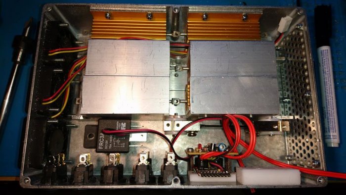
Finally last week all needed parts came in so I could build on.
The case does get crowded.
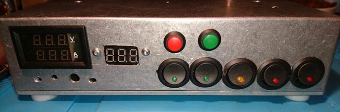
How the front will look like
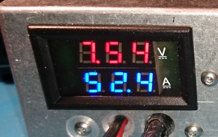
First test with a half charged battery
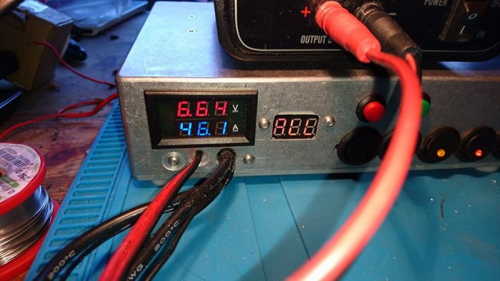
And with a full charged battery:
And here a movie with on the end how it shuts off when the voltage has reachred
https://youtu.be/xKiPhEZcbWw
One thing I have to change is connect the cooling fans directly to the 12v. Now they are switched with the load but when it shuts off the heat will rise a lot.
The case does get crowded.
How the front will look like
First test with a half charged battery
And with a full charged battery:
And here a movie with on the end how it shuts off when the voltage has reachred
https://youtu.be/xKiPhEZcbWw
One thing I have to change is connect the cooling fans directly to the 12v. Now they are switched with the load but when it shuts off the heat will rise a lot.
04-03-2018 | 10:58 AM
#11
Ok has anyone ever used (if you know what I�m about to describe) the automotive 1257 bulbs in a series discharger that a lot of us used back in the 90�s on NICAD & NIMH packs. Has anyone tried to use that type of discharger on a lipo pack I realize there�s no way to control each cell and you�d have to use a volt meter to make sure you didn�t ruin the battery but talk about a low tech low price discharger I understand this is crazy dangerous and I�m not asking anyone to do it so please don�t i was just curious as to if anyone has done it from a physical standpoint it should work fine while being supervised and a proper precaution taken as to cover all your variables of what can go wrong mainly fire. it�s just something I was fairly curious about and seen this post and figured I could ask here
08-13-2018 | 03:06 PM
#12
A very impressive build and DIY thread. If I had seen this first I may have gone in a different direction with my discharger!
I built a simple 15 amp discharger with two 1ohm 100W resistors, a voltage display, a PC heatsink and fan. I use it by plugging in the leads to the battery and simply monitoring the voltage with the display. When the battery gets to the point I want it discharged to, I disconnect the leads. Exceedingly simple and does require constant attention, but it still beats the lengthy discharge times of most chargers and gives you an easy way to build up some heat in the pack.
I built a simple 15 amp discharger with two 1ohm 100W resistors, a voltage display, a PC heatsink and fan. I use it by plugging in the leads to the battery and simply monitoring the voltage with the display. When the battery gets to the point I want it discharged to, I disconnect the leads. Exceedingly simple and does require constant attention, but it still beats the lengthy discharge times of most chargers and gives you an easy way to build up some heat in the pack.
Last edited by JC3; 08-13-2018 at 03:43 PM. Reason: heat comments.
08-13-2018 | 03:23 PM
#13
R/C Tech Elite Member
Joined: Mar 2006
Posts: 3,111
From: Ca
How much in parts, if you had to buy everything?
https://www.amainhobbies.com/gforce-...fc0270/p717457
$90 on sale
https://www.amainhobbies.com/gforce-...fc0270/p717457
$90 on sale
08-13-2018 | 03:54 PM
#14
How much in parts, if you had to buy everything?
https://www.amainhobbies.com/gforce-...fc0270/p717457
$90 on sale
https://www.amainhobbies.com/gforce-...fc0270/p717457
$90 on sale
08-13-2018 | 11:08 PM
#15
Thread Starter
Tech Lord
Joined: Aug 2007
Posts: 14,052
From: Holland
By then the the price of the SkyRC discharger and the total price of this project was arround 100 euro. So yes, I could buy the SkyRC which can only do 200w and monitors the total voltage while mine can do 500 watt max, monitors the voltage of each cell and switches off when the 1st cell will go under the programmed voltage.
And most of all ithe design and the fun to build is priceless
And most of all ithe design and the fun to build is priceless