


 142Likes
Icharger x6 Mini 30A Discharge
 11-19-2019, 06:08 PM
#301
Tech Adept
iTrader: (4)
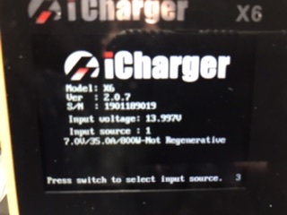
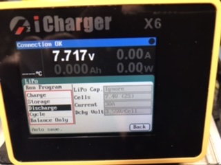
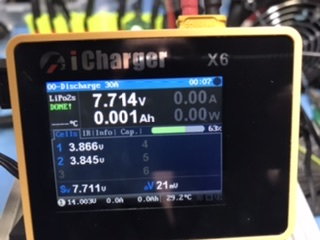
I can not for life of me get this to work. I have read every thread I can. Made my discharger as per instructions. X6 is set to "Not Regenerative". Downloaded the latest software (running 2.0.7). Watched every video I could. "Extra Discharge Enabled". When I go to discharge the amperage has gone as high as 3.2 but then the charger shuts off and says done. I see in the pictures that the voltage shown is very low. Do I need to set the low cutoff voltage somewhere and if so how is that done?
Only other thing I can think of now is the comment made about needing to run the newer beta software. Is this the problem I wonder? Where do I get this beta software? The Junsi Console just has the 2.0.7 firmware.
Only other thing I can think of now is the comment made about needing to run the newer beta software. Is this the problem I wonder? Where do I get this beta software? The Junsi Console just has the 2.0.7 firmware.
 11-19-2019, 06:19 PM
#302
I can not for life of me get this to work. I have read every thread I can. Made my discharger as per instructions. X6 is set to "Not Regenerative". Downloaded the latest software (running 2.0.7). Watched every video I could. "Extra Discharge Enabled". When I go to discharge the amperage has gone as high as 3.2 but then the charger shuts off and says done. I see in the pictures that the voltage shown is very low. Do I need to set the low cutoff voltage somewhere and if so how is that done?
Only other thing I can think of now is the comment made about needing to run the newer beta software. Is this the problem I wonder? Where do I get this beta software? The Junsi Console just has the 2.0.7 firmware.
Only other thing I can think of now is the comment made about needing to run the newer beta software. Is this the problem I wonder? Where do I get this beta software? The Junsi Console just has the 2.0.7 firmware.
 11-19-2019, 07:14 PM
#304
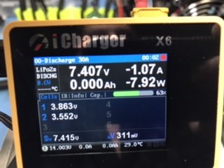
am I reading that wrong or does it look like it went up and not down?
11-20-2019, 12:01 AM
#305
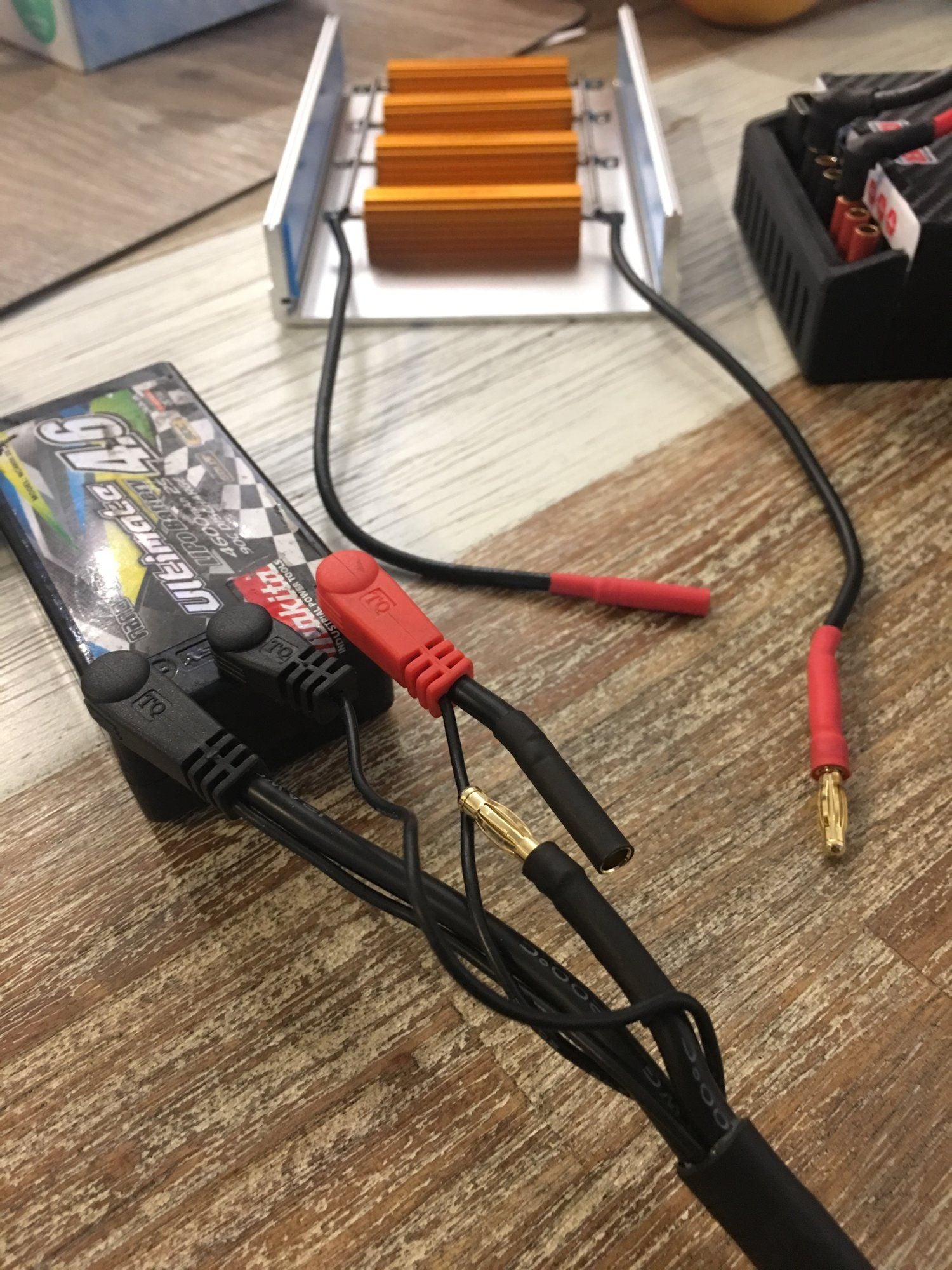
VanBee you need to wire up your discharge bank so that the balance leads are still connected directly to the battery.
 11-20-2019, 08:53 AM
#310
Icharger x6 Mini 30A Discharge
Last edited by mushroomed; 11-20-2019 at 09:15 AM.
11-20-2019, 08:58 AM
#311
Just my guess.
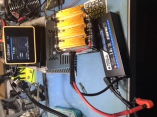
Question to everyone; Are you guys using any thermal paste between your resistors and heat sinks for the discharge banks? I am trying to figure out a design where I can use my old much more thermal electric motor cooler to cool the resisters, just haven't decided on the layout.
11-20-2019, 09:07 AM
#312
I used thermally conductive double sided tape to mount the resistors.
11-20-2019, 11:06 AM
#313
Tech Adept
iTrader: (4)
That�s the balance connector, but notice the thin wires running along the red and black 4/5mm connectors on your charge lead? These are telling the charger the voltage and resistance of the individual cells. Your black lead is connected to the discharge bank so the charger sees one cell with huge resistance (the discharge bank) and that skews the voltage of that cell too. Check out my post from earlier in the thread with the same problem, same charge lead and a solution:
Icharger x6 Mini 30A Discharge
AaHaa!!! I see the difference. I will try that later this evening. Hopefully that works.
What do you do with the middle balance lead in a 1S application?
11-20-2019, 11:19 AM
#314