


 1Likes
New project comes alive.
 06-30-2012 | 03:11 PM
#1
Thread Starter
Tech Lord

Joined: Aug 2007
Posts: 14,045
From: Holland
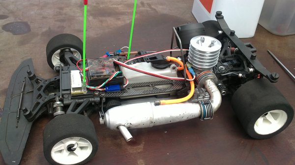
Not compleetly finished but the first test was a succes:
http://www.youtube.com/watch?feature...&v=zQH8KL8_J7M
Saddly the G-force sensors freak out just by the vibration of the engine but I will try to damp those peak vibrations. Here the engine was just running in hitting the 2nd gear arround 80km/h.
Look what is happening at 4:45 when making a pitstop.
http://www.youtube.com/watch?feature...&v=zQH8KL8_J7M
Saddly the G-force sensors freak out just by the vibration of the engine but I will try to damp those peak vibrations. Here the engine was just running in hitting the 2nd gear arround 80km/h.
Look what is happening at 4:45 when making a pitstop.
 07-01-2012 | 10:08 AM
#2
Tech Master
Joined: Apr 2010
Posts: 1,098
Not compleetly finished but the first test was a succes:
http://www.youtube.com/watch?feature...&v=zQH8KL8_J7M
Saddly the G-force sensors freak out just by the vibration of the engine but I will try to damp those peak vibrations. Here the engine was just running in hitting the 2nd gear arround 80km/h.
Look what is happening at 4:45 when making a pitstop.
http://www.youtube.com/watch?feature...&v=zQH8KL8_J7M
Saddly the G-force sensors freak out just by the vibration of the engine but I will try to damp those peak vibrations. Here the engine was just running in hitting the 2nd gear arround 80km/h.
Look what is happening at 4:45 when making a pitstop.
 07-01-2012 | 10:33 AM
#3
Thread Starter
Tech Lord
Joined: Aug 2007
Posts: 14,045
From: Holland
Indeed as expected but not much talked about on the forums.....
This is giving a clear sight that a quick temp messurement is needed when comming into the pits.
We have checked it with an Exergen temp meter and it is only a few degrees of. This electronic temperature sensor is calibrated to put out 10mV/C so it must be pretty close to real.
More info:
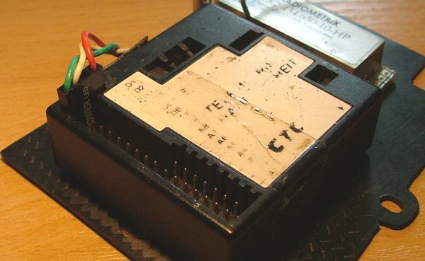
The main computer:
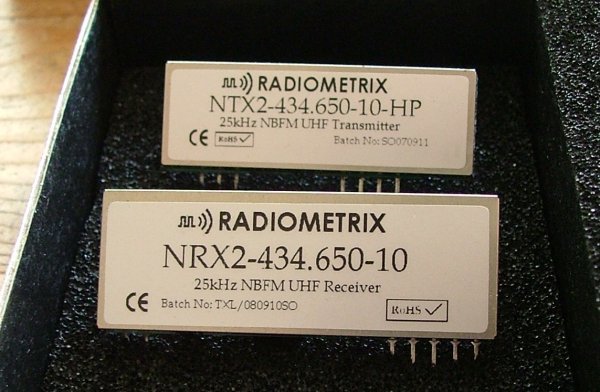
The TX/RX set:
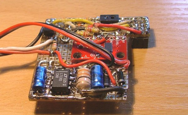
airtemp, humidity, g-forces, rpm sensor and a 6-12v voltage converter on one PCB which can be pushed up on the main computer.
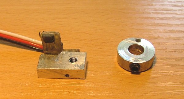
Basic setup with tempsens on a sleeve
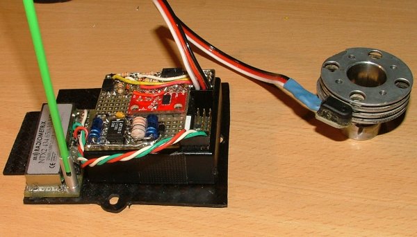
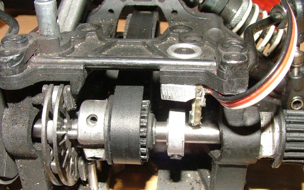
RPM sensor on gearbox shaft:
2 antenna's
the right spot to messure temp:
The receiver:
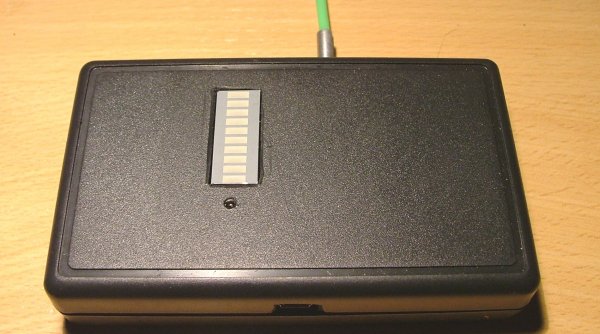
Internal
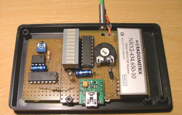
The telemetry computer is sending out a RS232 data signal which is directly transmitted over 433mhz and in the receiver again made to a clear digital signal going into an RS232-USB converter to fit all laptops and smaller.
This is giving a clear sight that a quick temp messurement is needed when comming into the pits.
We have checked it with an Exergen temp meter and it is only a few degrees of. This electronic temperature sensor is calibrated to put out 10mV/C so it must be pretty close to real.
More info:
The main computer:
The TX/RX set:
airtemp, humidity, g-forces, rpm sensor and a 6-12v voltage converter on one PCB which can be pushed up on the main computer.
Basic setup with tempsens on a sleeve
RPM sensor on gearbox shaft:
2 antenna's
the right spot to messure temp:
The receiver:
Internal
The telemetry computer is sending out a RS232 data signal which is directly transmitted over 433mhz and in the receiver again made to a clear digital signal going into an RS232-USB converter to fit all laptops and smaller.
07-02-2012 | 01:35 AM
#5
Thread Starter
Tech Lord
Joined: Aug 2007
Posts: 14,045
From: Holland
As mentioned the g-force sensor has to much influence of the vibrations in the chassis. Even when the engine running idle the sensor is messuring forces up to the 6G. I must find a way to filter them out and I think I know how.....
07-02-2012 | 06:45 AM
#6
Tech Master
Joined: Apr 2010
Posts: 1,098
Not compleetly finished but the first test was a succes:
http://www.youtube.com/watch?feature...&v=zQH8KL8_J7M
Saddly the G-force sensors freak out just by the vibration of the engine but I will try to damp those peak vibrations. Here the engine was just running in hitting the 2nd gear arround 80km/h.
Look what is happening at 4:45 when making a pitstop.
http://www.youtube.com/watch?feature...&v=zQH8KL8_J7M
Saddly the G-force sensors freak out just by the vibration of the engine but I will try to damp those peak vibrations. Here the engine was just running in hitting the 2nd gear arround 80km/h.
Look what is happening at 4:45 when making a pitstop.
 07-02-2012 | 08:17 AM
#8
Thread Starter
Tech Lord
Joined: Aug 2007
Posts: 14,045
From: Holland
Yes thanx!
I had some troubles getting a good signal, I have tryed several things and at the end I could see that the digital signal out of the receiver was not as clear as it should be, lucky there was also a low voltage analogue signal comming out which I could use to make it into a square wave digital signal. Probably the internal converter can not handle the low 2400bps baudrate.
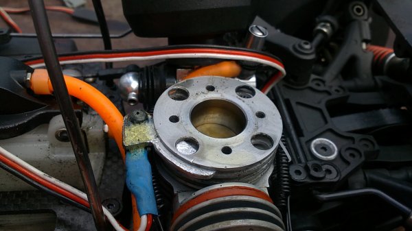
Next step is a 2nd rpm sensor directly on the flywheel and I want to messure the fueltemp and with that the influence of an exhaust cooler.
The main computer has 8 analogue, 8 digital (on/off) and 1 timer input and sends out a 2400 baud RS232 signal. The timer input is taking one rpm sensor, the signal from the future 2nd rpm sensor must be converted into a voltage but that is no problem. Currently the rpm sensor on the gearbox shaft is calculated to speed and engine RPM.
All is transmitted on a 25mW 433mhz transmitter and the specs are saying it can reach 500 meter which is more than enough, a simple signal strength meter on the receiver is telling that there is no issue in the far corners of the track.
Some things is a matter of learning and with 2 messurements per second maybe to slow but the graphis and numbers do tell enough. Looking at the speed you can see the behavour of the track, the throttle response and the moment of switching into 2nd gear. With such information you can compare and see improvements.
I had some troubles getting a good signal, I have tryed several things and at the end I could see that the digital signal out of the receiver was not as clear as it should be, lucky there was also a low voltage analogue signal comming out which I could use to make it into a square wave digital signal. Probably the internal converter can not handle the low 2400bps baudrate.
Next step is a 2nd rpm sensor directly on the flywheel and I want to messure the fueltemp and with that the influence of an exhaust cooler.
The main computer has 8 analogue, 8 digital (on/off) and 1 timer input and sends out a 2400 baud RS232 signal. The timer input is taking one rpm sensor, the signal from the future 2nd rpm sensor must be converted into a voltage but that is no problem. Currently the rpm sensor on the gearbox shaft is calculated to speed and engine RPM.
All is transmitted on a 25mW 433mhz transmitter and the specs are saying it can reach 500 meter which is more than enough, a simple signal strength meter on the receiver is telling that there is no issue in the far corners of the track.
Some things is a matter of learning and with 2 messurements per second maybe to slow but the graphis and numbers do tell enough. Looking at the speed you can see the behavour of the track, the throttle response and the moment of switching into 2nd gear. With such information you can compare and see improvements.
 07-02-2012 | 12:11 PM
#10
Thread Starter
Tech Lord
Joined: Aug 2007
Posts: 14,045
From: Holland
The g-force sensor is a 3 axis type so yes, I can use the Z-axis to tune dampers but again I have to take care of filtering out the vibrations, so far with this I can see how well balanced the engine is 
07-02-2012 | 03:26 PM
#11
Joined: Sep 2010
Posts: 3,569
From: My house.
Thanks for the explanation.Well the update rate is too slow for the speed/acceleration/reaction of RC cars but good nevertheless,have you considered writing to a SD card for output instead of using RF?The box would directly write all data into a RAW file,just a bunch of vectors,one for each sensor with 2 rows that considering one row=.5sec and append more 2 rows and so on each cycle.Don't know if that should help if the bottleneck is at the RS232 converter though.
The applications are just staggering,can be used for engine/clutch/FDR efficiency;damper performance analysis,body/tires analysis...Congratulations Roelof,the RC world is one step closer to understand Roll Centers
The applications are just staggering,can be used for engine/clutch/FDR efficiency;damper performance analysis,body/tires analysis...Congratulations Roelof,the RC world is one step closer to understand Roll Centers
07-02-2012 | 03:59 PM
#12
Thread Starter
Tech Lord
Joined: Aug 2007
Posts: 14,045
From: Holland
Involved with an engine devellopping (the sleeve and the engine are on the pics) we come to a point that real numbers and such graphics can tell more than only a feeling. With 8 analoge inputs you can connect any sensor with an analogue output and with that you can understand more what is happening in the car.
Currently the main computer is huge, it also a product from back in 1995 and the Win 3.1 program is still working fine on any current 32 bit Windows and has all the needs to make it work. Recording on a memory module will not make it faster but it is possible. Now the pitman can follow the realtime data while it is still recorded at the background. At home you can finetune the scaling and analyse the data and I must say that it is fun.
A next step can be an Arduino: http://arduino.cc/en/Main/Hardware
This Atmel128/328 chip loaded with a special open source bootloader has the same function as my old Motorola 68HC05B6 processor but due the open source easy to find applications. It can even handle more sensors, the digital inputs can even handle sensors with a serial digital output.
I just got mail from the manufacturer of the G-force sensors, they say it can work better with an active filter but they do advice a different sensor. hmmmm.....
07-02-2012 | 11:34 PM
#15
Thread Starter
Tech Lord
Joined: Aug 2007
Posts: 14,045
From: Holland
I did take a look at the Hitec set, that one has also a black box to connect a lot of sensors and a data-out which could be modified for own applications.