


 6Likes
HPI Sprint 2 Mods
 05-27-2012, 04:01 PM
#16
Everyone has their own voodoo. This is my voodoo. This is what works for me.
Click on thumbnails for larger pictures.
Steering Slop – Loose Ball Cups
Loose Ball Cups –
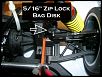
The EASIEST FIX METHOD = Punch out 5/16” diameter disks (or cut 5/16” pieces) of a Zip Lock Bag.
Install one disk (or piece) centered over each ball studs.
Carry spares = nothing lasts forever.
OR
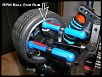
Another surefire way = use RPM Heavy Duty Ball Ends.
They come in different colors.
Scroll down to the 4-40 Ends. That's what the S2S uses.
http://www.rpmrcproducts.com/product...c/steering.htm
NOTE 1: RPM Ball Cups – When you install these they will be TIGHT. One way to free them up a bit without compromising their integrity is to use some Powdered Graphite inside them, attach each end separately and work the ball cup around the ball stud repeatedly. Knock out excess graphite afterwards.
NOTE 2:THE RIMS MAY RUB ON THE RPM BALL CUPS –
Use RPM 80202 (6mm) Hex Nut Adapters on the front axles.
These will also give the front wheels a wider stance & give you a tighter turning radius.
Only my left front wheel was rubbing.
I'm using RPM 80202 6mm Hex Nut Adapters on the front with the zero offset vintage wheels so the rub was near the edge of the rim = I took a file to my RPM Ball End & I lightly sanded the inside of the wheel where it was rubbing.
I also marked the top of the ball end with a magic marker afterwards.
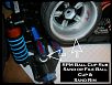
Problem solved.
No problem on the rears / Here I use the 3mm offset vintage wheels with the oem HPI Hex Nut Adapters & I'm still using the oem HPI Ball Cups with a Zip Lock Bag disk in each ball cup to take up the slop.
NOTE 3: The RPM 80202 6mm Hex Nut Adapters WILL NOT work on the axles IF you are using anything other than Standard ZERO OFFSET RIMS. Especially 31mm Rims with a 3 offset.
IF you’re running VTA rims do NOT use the RPM 6mm Hex Nut Adapters on the rear - the tires will rub on the body.
*Additionally, the configuration of the RPM 80202 6mm Hex Nut Adapters when compared to the HPI Hex Nut Adapters differs slightly on the mating end. The HPI oem hex nut adapters protrude a bit to bear on the inner bearing race. The RPM adapters do not have this protrusion. Therefore, when tightening the axle nuts after shimming, care must be take to not over tighten = you will bind the axle.
If you want a tighter turning radius still - you can set your front toe to –1° and sand or file off 50% of the hub stop on the C Blocks – Don’t forget to reset your end points using the lower front shock eyes as your reference point.
NOTE 4: If you use the 6mm adapters and you're running a VTA body chances are may have to set the body higher on the posts so the front tires don't rub.
Click on thumbnails for larger pictures.
Steering Slop – Loose Ball Cups
Loose Ball Cups –
The EASIEST FIX METHOD = Punch out 5/16” diameter disks (or cut 5/16” pieces) of a Zip Lock Bag.
Install one disk (or piece) centered over each ball studs.
Carry spares = nothing lasts forever.

OR
Another surefire way = use RPM Heavy Duty Ball Ends.
They come in different colors.
Scroll down to the 4-40 Ends. That's what the S2S uses.
http://www.rpmrcproducts.com/product...c/steering.htm
NOTE 1: RPM Ball Cups – When you install these they will be TIGHT. One way to free them up a bit without compromising their integrity is to use some Powdered Graphite inside them, attach each end separately and work the ball cup around the ball stud repeatedly. Knock out excess graphite afterwards.
NOTE 2:THE RIMS MAY RUB ON THE RPM BALL CUPS –
Use RPM 80202 (6mm) Hex Nut Adapters on the front axles.
These will also give the front wheels a wider stance & give you a tighter turning radius.
Only my left front wheel was rubbing.

I'm using RPM 80202 6mm Hex Nut Adapters on the front with the zero offset vintage wheels so the rub was near the edge of the rim = I took a file to my RPM Ball End & I lightly sanded the inside of the wheel where it was rubbing.
I also marked the top of the ball end with a magic marker afterwards.

Problem solved.
No problem on the rears / Here I use the 3mm offset vintage wheels with the oem HPI Hex Nut Adapters & I'm still using the oem HPI Ball Cups with a Zip Lock Bag disk in each ball cup to take up the slop.
NOTE 3: The RPM 80202 6mm Hex Nut Adapters WILL NOT work on the axles IF you are using anything other than Standard ZERO OFFSET RIMS. Especially 31mm Rims with a 3 offset.
IF you’re running VTA rims do NOT use the RPM 6mm Hex Nut Adapters on the rear - the tires will rub on the body.
*Additionally, the configuration of the RPM 80202 6mm Hex Nut Adapters when compared to the HPI Hex Nut Adapters differs slightly on the mating end. The HPI oem hex nut adapters protrude a bit to bear on the inner bearing race. The RPM adapters do not have this protrusion. Therefore, when tightening the axle nuts after shimming, care must be take to not over tighten = you will bind the axle.
If you want a tighter turning radius still - you can set your front toe to –1° and sand or file off 50% of the hub stop on the C Blocks – Don’t forget to reset your end points using the lower front shock eyes as your reference point.
NOTE 4: If you use the 6mm adapters and you're running a VTA body chances are may have to set the body higher on the posts so the front tires don't rub.
Last edited by Marv; 06-27-2014 at 03:13 PM. Reason: Info updated
 06-24-2012, 09:51 AM
#17
Optional Left Crank Mod / Slop Fix
NEEDED
1 - M3x35mm Flat Head Phillips Screw
3 - M3 Lock Nuts - Dubro #2101
2 - 3x8x3 Bearings
Ruler
Remove the upper deck.
Remove the left crank assembly.
Remove the shaft.
Measure the distance from the bottom of the shaft to the step that the bearing sits on = this is the height of the second screw you will be installing.
Run the M3x35mm Flat Head Phillips Screw up through the chassis and install a M3 Lock Nut as shown (tapered end facing up) - Tighten it down good.
Install another M3 Lock Nut as shown (tapered end face up).
The position of this lock nut on the screw will determine the height of the crank.
Install the left crank assembly, with the new bearings in place.
Install the last M3 Lock Nut as shown (tapered end facing down).
Click thumbnail for larger picture
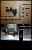
Installing the lock nuts as shown brings pressure on the inner races of the bearings.
Proper adjustment = reduced slop and wobble in the left crank assembly.
DO NOT OVER TIGHTEN the top lock nut!
Adjust the top lock nut so that the bearing slop is nil and the crank doesn't bind when moved through it's operating range.
Reinstall upper deck and linkage. You'll notice that the M3x35mm screw comes up through the upper deck hole. This is not a bad thing - on the offside chance that the first lock nut should come loose while your driving (highly improbable) the extra length coming up through the deck will help stabilize the assembly somewhat till repairs can be made.
When compared to the previously posted left crank mod, this one is cheaper & tighter.
NOTE: The FRONT C HUB / KNUCKLE / CONTROL ARM & REAR HUB slop fixes are almost complete and will be posted soon.
Last edited by Marv; 10-15-2012 at 01:36 PM. Reason: Content added
 06-24-2012, 05:32 PM
#19
Tech Adept
iTrader: (5)
Join Date: Apr 2012
Location: Everett WA in the Summer Mesa AZ in the Winter
Posts: 128
Trader Rating: 5 (100%+)
Anyone having servo problems with their Sport 2. I'm running a Spektrum 3100 RX and use DX3R TX. Put new RPM's on the front and worked them in Per Marvs recommendation. Thought things were too tight cause steering didn't want to center every time. Took Servo arm loose and Servo did same thing with no load. Changed to a Hitec 645 and things seemed better but at race today same thing started happening. Also noticed ESC was getting real warm on the side just working the servo. Do I need a BEC or a new ESC or????? I thought I read somewhere that the Spektrum RX's use a lot of power compared to others and this along with the added load of tighter steering may be the issue. I will try putting the HPI RX back in and see what happens.
06-24-2012, 05:50 PM
#20
That's a good question Stanfsu and it deserves a good answer. Unfortunately, I don't have one.
My intention is to run my S2S in VTA & TC once I get it tightened, I get my skill level back up and I upgrade to the 25.5 motor & esc.
I still have the OEM brushed 15T Firebolt and esc in mine.
Right now I'm geared at 4.56 using 48 pitch 84/39 & that gets me around the high school tennis courts for now.
OBTW, when calculating your FDR the magic number for the equation is 2.13
Example: (122/35) X 2.13 = Final Drive Ratio of 7.42
This link might be helpful - Gearing a Sprint 2 for VTA -
Last edited by Marv; 07-20-2012 at 02:16 AM.
06-24-2012, 07:16 PM
#21
Tech Adept
iTrader: (1)
Great thread...
I'd like to add one more tip:
The original sprint 1 had a much nicer steering assembly. On that one the left side is sandwiched between the chassis and top deck (the pivot post where it rotates runs all the way from chassis to top deck, holding the assembly firmly) so it does not have the problem the sprint 2 assembly has (because sprint2 bearing has no support other than the lower chassis, with no upper support). You can still get them new on ebay. A few months ago they were on towerhobbies too, but it's no longer the case.
Part # is HPI 86005
http://www3.towerhobbies.com/cgi-bin...?&I=LXDHR8&P=7
here's the steering assembly exploded view for the sprint1 in case you're wondering, and a picture of that chassis. You can see how it fits in there. Part is a direct fit to the sprint2 chassis. In fact, sprint 2 uses a lot of the sprint 1 parts.
cheers all
06-24-2012, 07:18 PM
#22
Anyone having servo problems with their Sport 2. I'm running a Spektrum 3100 RX and use DX3R TX. Put new RPM's on the front and worked them in Per Marvs recommendation. Thought things were too tight cause steering didn't want to center every time. Took Servo arm loose and Servo did same thing with no load. Changed to a Hitec 645 and things seemed better but at race today same thing started happening. Also noticed ESC was getting real warm on the side just working the servo. Do I need a BEC or a new ESC or????? I thought I read somewhere that the Spektrum RX's use a lot of power compared to others and this along with the added load of tighter steering may be the issue. I will try putting the HPI RX back in and see what happens.
Some people use captured ball ends - which ones and where to find them appears to be another well kept secret - until I find some that fit and work I won't be writing about them.
My steering is frog jacked / the right side differs slightly from the left = not SYMETRICAL.
And the OEM chassis is warped.
The OEM servo is weaker once the steering is tightened and slow as well.
I upgrade to a - Savox 1257 - BUT I had to make a new servo mounting block for one side because the HPI servo is way longer than any other servos.


If you have one end of your servo flopping around like a fart in a wind storm that may be a problem.
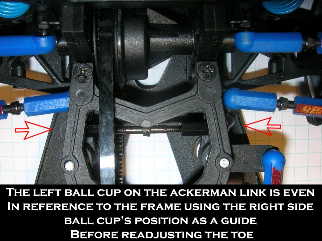
I also upgarded my Ackerman link to an adjustable one and realigned the cranks to be more centered.
Disconnect the servo link and make sure you have no binding in the steering system.
Make sure the servo horn is as 12 o'clock as you can get it with the servo cenetered in the neutral position.
Initially, I didn't have the servo horn installed correctly after insatlling the Savox - horn at 12 o'clock centered with servo centered - and had the same issue as before - not returning to center.
I reinstalled the servo horn properly and that seemed to take care of the return to center problem.
I removed the end of the servo link (at the servo) to the servo saver - turned on Tx then the Rx - the servo centered - I shut of Rx centered and reinstalled the horn. Then I reinstalled the link and readjusted the servo to servo saver link. The OEM servo has a shorter throw than the Savox @ 60 degrees.
HPI Racing HPI SF-10W Servo / OEM servo specs =
Voltage Range: 4.8 - 6.0V
Torque: 36.10oz/in (4.5kg/cm) @ 6.0V
Speed: 0.18 sec/60° @ 6.0V
Length: 1.9" (47.8mm)
Width: 0.79" (20mm)
Height: 1.4" (36mm)
Operating angle = unknown
Savox 1257 specs =
Dimensions(mm): 40.3x20.2x37.2
Weight(g): 52.4
Speed(@4.8V sec/60): .09
Torque(@4.8V oz-in): 111.1
Speed(@6.0V sec/60): .07
Torque(@6.0V oz-in): 138.9
Gear: Titanium & Aluminum
Bearing: 2BB
Case: Aluminum
25 Tooth Spline
Operating angle 60 degrees = longer throw
The 1257 is faster and has more torque, but it’s a power hungry little bugger - sucked my Plasma 2000 OEM battery down in no time... the steering glitched left and SMACK! Right into a steel post. Lucky for me I had glassed the front end of the body - so I only got a ding in the fender, spit out a body post pin and jacked the right front toe out a bit.
I have a capacitor now...

I installed the Associated LRP BEC Stabilizing Capacitor part #LRP80135 and a LiPo = no problems. $10 = cheap insurance.
Here's another option for a servo - S6040 Digital Surface Servo - High Speed [SPMSS6040] -
From what I've read so far the s6040 isn't power hungry like the Savox servos, but I'd cap it anyway to be on the safe side.
Hitec HS-645MG specs =
Speed: 0.24 sec/60° at 4.8V
0.20 sec/60° at 6.0V
Torque: 106.93 oz-in at 4.8V (7.7 kg-cm)
133.31 oz-in at 6.0V (9.6 kg-cm)
Length: 1.59" (40.6mm)
Width: 0.77" (19.8mm)
Height: 1.48" (37.8mm)
Weight: 2.11oz (60g)
Operating angle is 45 degrees = shorter throw
Damned good torque, but slower than the OEM and a short throw.
Last edited by Marv; 06-30-2012 at 09:48 AM.
06-24-2012, 07:42 PM
#23
Great thread...
I'd like to add one more tip:
The original sprint 1 had a much nicer steering assembly. On that one the left side is sandwiched between the chassis and top deck (the pivot post where it rotates runs all the way from chassis to top deck, holding the assembly firmly) so it does not have the problem the sprint 2 assembly has (because sprint2 bearing has no support other than the lower chassis, with no upper support). You can still get them new on ebay. A few months ago they were on towerhobbies too, but it's no longer the case.
Part # is HPI 86005
http://www3.towerhobbies.com/cgi-bin...?&I=LXDHR8&P=7
here's the steering assembly exploded view for the sprint1 in case you're wondering, and a picture of that chassis. You can see how it fits in there. Part is a direct fit to the sprint2 chassis. In fact, sprint 2 uses a lot of the sprint 1 parts.
cheers all
I'd like to add one more tip:
The original sprint 1 had a much nicer steering assembly. On that one the left side is sandwiched between the chassis and top deck (the pivot post where it rotates runs all the way from chassis to top deck, holding the assembly firmly) so it does not have the problem the sprint 2 assembly has (because sprint2 bearing has no support other than the lower chassis, with no upper support). You can still get them new on ebay. A few months ago they were on towerhobbies too, but it's no longer the case.
Part # is HPI 86005
http://www3.towerhobbies.com/cgi-bin...?&I=LXDHR8&P=7
here's the steering assembly exploded view for the sprint1 in case you're wondering, and a picture of that chassis. You can see how it fits in there. Part is a direct fit to the sprint2 chassis. In fact, sprint 2 uses a lot of the sprint 1 parts.
cheers all
Great addition for options, too.
Don't hesitate to add more if ya got 'em.
All voodoo is welcome here.
RC Planet has the - HPI86005 - steering set.
From what I can determine the major slop on the S2 is the shaft to inner bearing races and then the bearing slop - inner race to balls to outer race. I tried ceramic hybrid bearings and had the same slop. I suppose a higher grade of bearings or sealed bearings might help. HPI added a heavy duty spring to the servo saver crank on the S2 version - that applies upward pressure to the bearings, forcing the bearings upward and virtually eliminating the slop. I tried to spring the left crank = no success.
Last edited by Marv; 07-06-2012 at 05:16 AM.
06-24-2012, 07:50 PM
#24
Tech Adept
iTrader: (1)
The sprint 1 had the captured ball ends, take a look at the picture I posted. Beautiful system with virtually no play in them. Unfortunately those have been discontinued a long time ago.
best thing I like about the sprint2 is the worry free transmission due to the steel gears in the differentials. I don't have a lot of time to wrench on the cars so this is a big plus for me.
By the way, another thing to keep in mind: you can put in differential oil to replace the grease in the diff box. this will make a smoother diff. On the front diff i use a very heavy diff oil (almost like clay) this makes the diff behave almost like it's locked but still allows some diff action.
If you put diff oil make sure your sprint comes with the small o-rings meant for the diff boxes (there should be a total of 3 o-rings for each diff case: 1 large and 2 small ones). I think on some RTRs the small ones are not installed, so it is important to check that otherwise the diff oil will leak.
Part# is HPI 86016 , that one comes with all o-rings for the 2 diff cases.
06-24-2012, 08:17 PM
#25
Yes, I've tried to look for those but haven't found a match. There's the dubro brand but they are too long. perhaps they can be made to fit, not sure.
The sprint 1 had the captured ball ends, take a look at the picture I posted. Beautiful system with virtually no play in them. Unfortunately those have been discontinued a long time ago.
best thing I like about the sprint2 is the worry free transmission due to the steel gears in the differentials. I don't have a lot of time to wrench on the cars so this is a big plus for me.
By the way, another thing to keep in mind: you can put in differential oil to replace the grease in the diff box. this will make a smoother diff. On the front diff i use a very heavy diff oil (almost like clay) this makes the diff behave almost like it's locked but still allows some diff action.
If you put diff oil make sure your sprint comes with the small o-rings meant for the diff boxes (there should be a total of 3 o-rings for each diff case: 1 large and 2 small ones). I think on some RTRs the small ones are not installed, so it is important to check that otherwise the diff oil will leak.
Part# is HPI 86016 , that one comes with all o-rings for the 2 diff cases.
I had a couple laying around so I tried them on the S2 = I'm gonna pass for now use the RPM's.
Which oil do you use in your diff?
I have a spare diff coming in to mess around with.
I picked up 2 - HPI 72215 GEAR DIFF ADJUSTMENT SPRING SETS - to see if they do any good.
I also read somewhere that packing the diff with - Mobil 1 Red Synthetic Grease - (I think this is the one) works well also.
Last edited by Marv; 10-05-2012 at 06:47 PM.
06-24-2012, 08:49 PM
#26
Tech Adept
iTrader: (1)
Marv,
I have used 300,000 wt diff oil for the front, did i mention it is THICK?
I got that one from a store in japan (rcchamp) only thing readable in the bottle is "mumeisha" so that must be the brand.
For the rear diff I'm using 3,000 wt
I also heard that for the front diff there is some sort of clay or putty that is really good and would achieve the same effect. It is used in the graphics/art industry as an eraser (you rub this in your drawings and it absorbs the graphite without leaving any residue). I can't recall the name right now but it is not pencil eraser; It is a special putty. From what i hear that would be the best to get a tight diff.
have you made the chassis mods to save the belts from getting shred by small pebbles? that is a good one too, specially for those running on non prepped surfaces such as parking lots. The new sprint 2 flux chassis has the required holes to get the pebbles out instead of getting them sandwiched between the belts and chassis. The holes are just below the diff boxes, the older sprint2 chassis did not come with it so it's advisable to put those in.
will try to contribute more tips as i recall them... My current sprint is on storage, dissasembled and awaiting a full rebuild. just haven't had the time for it...
06-24-2012, 09:41 PM
#27
Tech Adept
iTrader: (5)
Join Date: Apr 2012
Location: Everett WA in the Summer Mesa AZ in the Winter
Posts: 128
Trader Rating: 5 (100%+)
I had the same problem with my OEM servo - only it did it before I tightened the steering = crap right out of the box and it got worse after I tightened the steering.
Some people use captured ball ends - which ones and where to find them appears to be another well kept secret - until I find some that fit and work I won't be writing about them.
My steering is frog jacked / the right side differs slightly from the left = not SYMETRICAL.
And the OEM chassis is warped.
The OEM servo is weak once the steering is tightened and slow as well.
I upgrade to a - Savox 1257 - BUT I had to make a new servo mounting block for one side because the HPI servo is way longer than anyone other servos.
Thanks Marv. Great info.
I only used the Hitec cause I had it and to eliminate the HPI servo as the problem which I thought I had. I did all the centering of the Servo horn as you described. the BEC Cap sounds like a good idea. Because both servos had problems centering with the servo arms disconnected I think I have probably answered my own question. I think the Servos coupled with the Spektrum RX may be too much for the BEC in the HPI ESC. Will try to confirm tonight.
I do need to finish off the front suspension as you have with the stabilization of the left servo post but just the RPM ends made a tremendous improvement when it did steer.
I noticed that you have your servo saver spring quite a ways up. I backed mine off till I could just see light between the bottom of the knob and the chassis to see if that helped servo centering and it didn't. Is there is an optimum location for it.
06-25-2012, 12:05 AM
#28
Marv,
I have used 300,000 wt diff oil for the front, did i mention it is THICK?
I got that one from a store in japan (rcchamp) only thing readable in the bottle is "mumeisha" so that must be the brand.
For the rear diff I'm using 3,000 wt
I also heard that for the front diff there is some sort of clay or putty that is really good and would achieve the same effect. It is used in the graphics/art industry as an eraser (you rub this in your drawings and it absorbs the graphite without leaving any residue). I can't recall the name right now but it is not pencil eraser; It is a special putty. From what i hear that would be the best to get a tight diff.
have you made the chassis mods to save the belts from getting shred by small pebbles? that is a good one too, specially for those running on non prepped surfaces such as parking lots. The new sprint 2 flux chassis has the required holes to get the pebbles out instead of getting them sandwiched between the belts and chassis. The holes are just below the diff boxes, the older sprint2 chassis did not come with it so it's advisable to put those in.
will try to contribute more tips as i recall them... My current sprint is on storage, dissasembled and awaiting a full rebuild. just haven't had the time for it...
I have used 300,000 wt diff oil for the front, did i mention it is THICK?
I got that one from a store in japan (rcchamp) only thing readable in the bottle is "mumeisha" so that must be the brand.
For the rear diff I'm using 3,000 wt
I also heard that for the front diff there is some sort of clay or putty that is really good and would achieve the same effect. It is used in the graphics/art industry as an eraser (you rub this in your drawings and it absorbs the graphite without leaving any residue). I can't recall the name right now but it is not pencil eraser; It is a special putty. From what i hear that would be the best to get a tight diff.
have you made the chassis mods to save the belts from getting shred by small pebbles? that is a good one too, specially for those running on non prepped surfaces such as parking lots. The new sprint 2 flux chassis has the required holes to get the pebbles out instead of getting them sandwiched between the belts and chassis. The holes are just below the diff boxes, the older sprint2 chassis did not come with it so it's advisable to put those in.
will try to contribute more tips as i recall them... My current sprint is on storage, dissasembled and awaiting a full rebuild. just haven't had the time for it...
I have the newer S2 with the redesigned chassis and bulkheads.

HPI addressed the closed diff bulkhead by redisgning the bulkhead HPI 85001 with out the cover. They should bolt right up on your S1 chassis.
06-25-2012, 12:37 AM
#29
The common complaint was that the nut would back itself off.
Heck, if you want it that tight you might as well JB Weld the damned thing in place.

So, I'm thinking to myself...Stuffing an extra spring in there makes no sense.
It defeats the purpose of a SERVO SAVER.
Which, I believe is if you smack something hard enough to snap off a wheel and strip the servo the servo saver is designed to give so that servo suffers less.
Could be why they call it a Servo Saver...
I have a piece of 8oz vegetable tanned under mine to keep it from backing off. That's about 1/8" thick. It just felt like a good place to adjust it to.
As far as an optimum location - where I have mine works for me, but I haven't smacked anything hard enough to knock the snot out of the servo... yet.
I suppose I'll find out how optimum it it is after a smack something hard enough to snap a wheel off.
Last edited by Marv; 07-06-2012 at 05:18 AM.
06-25-2012, 09:24 PM
#30
Tech Adept
iTrader: (5)
Join Date: Apr 2012
Location: Everett WA in the Summer Mesa AZ in the Winter
Posts: 128
Trader Rating: 5 (100%+)
Thanks Marv.
I played with the electronics today including going back to the HPI RX and TX. No real help so put the HPI servo back in; still no improvement. Went back to the Spektrum Rx and Tx setup and changed the Tx frame rate to 16.5 ms the slowest possible and things are normal again. Based on my driving skills the slower servo speed is probably better but still need to figure out whats going on. Think I'll try the capacitor next.
I played with the electronics today including going back to the HPI RX and TX. No real help so put the HPI servo back in; still no improvement. Went back to the Spektrum Rx and Tx setup and changed the Tx frame rate to 16.5 ms the slowest possible and things are normal again. Based on my driving skills the slower servo speed is probably better but still need to figure out whats going on. Think I'll try the capacitor next.