


 8Likes
Lap Timing Decoder


 03-05-2013 | 07:28 AM
#123
Kjrell, thanks for posting the photos!
Payalneg, here is a description of how to post photos:
http://www.rctech.net/forum/10334159-post102.html
Payalneg, here is a description of how to post photos:
http://www.rctech.net/forum/10334159-post102.html
03-06-2013 | 07:27 AM
#124
The code for the �Personal Lap Timer� (PLT) is now working.
The PLT reads the first valid transponder ID it sees after power-up, stores it to EEPROM, then calculates lap times for that transponder while ignoring all others. The results are sent via RS232 to an external computer.
The RS232 signal is currently logic-level, which doesn�t conform to the true specification (that requires voltages below -3V), but the PC I�m using has no problem reading the logic levels.
While I have saved the transponder ID to EEPROM, and recall the ID and send it via RS232 to make sure it got where it was supposed to go, I�m currently not using the value stored in the EEPROM for anything else. I intend on including a pushbutton to tell the microprocessor when to acquire the transponder ID so there will be no need to re-acquire it every time the decoder is powered-up (which is now a minor inconvenience).
The next (vitally important) step will be to test the system with transponders in moving cars, and modify things depending on the effects of interference from the motor, ESC, radio, etc.
I�ll post the last schematic, showing connections to the microprocessor, shortly.
03-06-2013 | 08:04 AM
#125
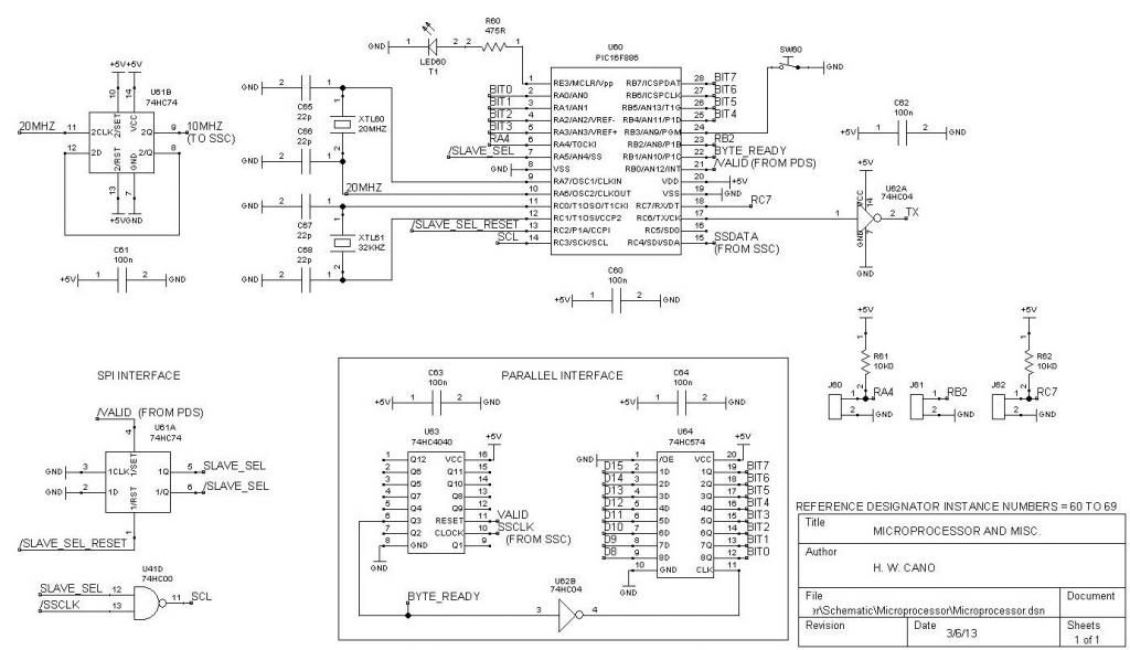
Here’s the schematic I promised earlier:
The microprocessor receives transponder data (stripped of the first two bytes by the Preamble Detector / Stripper, or PDS), timestamps it, and transmits the result as ASCII hexadecimal characters in asynchronous serial format to an external computer.
(Alternatively, I have also created software that recognizes a single transponder and calculates lap times for it, for use in testing and as a “Personal Lap Timer”.)
Microprocessor U60 runs at 20 MHz, as determined by crystal XTL60 and capacitors C65 and C66. (U60 is shown as a 28 pin PIC16F886; my prototype uses the 40 pin PIC16F887.) One of the internal counters runs at 32.00 KHz, as determined by crystal XTL61 and capacitors C67 and C68. This is used as a timebase for the timestamps.
U61B divides the 20 MHz clock down to 10 MHz for use in the Synchronous Serial Converter (SSC). (Thanks to Brano, “OM2KW”, for pointing out that the PIC oscillator will drive the counter when in HS mode.)
The prototype currently transfers the transponder data into the microprocessor using the components labeled “Parallel Interface”. When the code for the SPI interface is complete, these will be eliminated , and U61A and U41D will serve the purpose.
EDIT: For the latest schematics, see post 206:
http://www.rctech.net/forum/12118142-post206.html
Last edited by howardcano; 06-11-2013 at 08:11 AM.
03-07-2013 | 08:54 AM
#126
I've been re-investigating bringing the transponder data into the PIC on its SPI port, in an effort to eliminate the two ICs in the Parallel Interface (on the microprocessor schematic sheet). Unfortunately, there is an anomaly where every ninth bit in the data stream is ignored, regardless of whether or not the Slave Select pin is active. (The PIC has an option to either use or ignore the Slave Select). I've contacted Microchip about the problem.
According to my oscilloscope, all of the bits are being clocked in correctly to the PIC, and all setup, hold, and clock times are more than the minimum specifications.
The two ICs in the Parallel Interface don't use up much space or cost much money, so it's not a big deal if the SPI won't work. But it would be nice to understand what's going on!
03-09-2013 | 06:36 PM
#127
Keep up the Great work.
I am Waiting for some ATMEL AVR test
I personally think the AVR will resolve the SPI lost ninth bit problem.
Maybe next week I will start working on the Amplifiers.
PCB's for the Amplifiers would be nice but this project is still in its infancy.
Personally I like ExpressPCB for their Quality work but they are kinda pricey.
I think the entier timing and scoring system could be done on a ATMEGA128 /ATMEGA1280
I have nothing against PIC's I just code AVR's as a hobby.
Last edited by Skruger; 03-09-2013 at 06:42 PM. Reason: ugg spelling
03-09-2013 | 10:11 PM
#128
Suspended
iTrader: (2)
Joined: Dec 2011
Posts: 521
AMB, be afraid, be very afraid!
As a compromise between for profit and open source, you could try the "John Carmack" model. Sell it, make some money, and then give it away.
And once it's open source, it'll just get better and better.
You geeks are awesome!
As a compromise between for profit and open source, you could try the "John Carmack" model. Sell it, make some money, and then give it away.
And once it's open source, it'll just get better and better.
You geeks are awesome!
03-10-2013 | 04:23 AM
#129
It�s quite possible that changing over to the Atmel microprocessor will solve the SPI problem, probably because I won�t repeat the same mistake I�m making with the PIC-- whatever that mistake might be. But the biggest reason to change to the Atmel will be for the larger RAM (giving more space for the transmit FIFO).
If you happen to lay out a PC board, please feel free to share it with us!
I�ve used Advanced Circuits for many years. Several times they�ve gone way further than I would have expected with their help and support. It�s hard to find service like that these days.
03-10-2013 | 04:24 AM
#130
I don't think AMB has much to worry about. From what we've heard, RC is only a small market for them. Also, I believe that the decoders make much less money than the transponders!
I'll probably offer the programmed microprocessors at a nominal cost, just like I did on my transponder design. That might help recover some of my development expenses.
03-10-2013 | 05:16 AM
#131
Tech Initiate
Joined: Dec 2012
Posts: 48
SPI on shift register is better then SPI in AVR. Interrupt, return from interrupt writing data in SRAM is very many cycle of MCU. Detectors on 74hc logic os the best way.
Thanks to Howard for amplifier schematics. My device is working fine.
For example this device maked on ATMEGA128 with external 32kb RAM.
Detector if based on ATTINY2313 (this is my big mistake to do detectors on MCU)
Also it have ENC28J60 for Ethernet and Tp-link for WiFi.
I am waiting Howard chips to do compataible Amb chips with my decoder
h_ttp://i1277.photobucket.com/albums/y482/Payalneg/2013-03-10114721_zps9c9e45ba.jpg
h_ttp://i1277.photobucket.com/albums/y482/Payalneg/2013-03-10114729_zps0927950a.jpg
P.S. Can post images because: You are only allowed to post URLs to other sites after you have made a certain number of posts. You have not reached that limit yet.
03-10-2013 | 06:30 AM
#132
SPI on shift register is better then SPI in AVR. Interrupt, return from interrupt writing data in SRAM is very many cycle of MCU. Detectors on 74hc logic os the best way.
Thanks to Howard for amplifier schematics. My device is working fine.
For example this device maked on ATMEGA128 with external 32kb RAM.
Detector if based on ATTINY2313 (this is my big mistake to do detectors on MCU)
Also it have ENC28J60 for Ethernet and Tp-link for WiFi.
I am waiting Howard chips to do compataible Amb chips with my decoder

 03-10-2013 | 02:23 PM
#133
Tech Adept
Joined: Jan 2013
Posts: 104
About transponders, I've read here on R/C Tech that AMB ones should cost less then 25$ based on components used (bought by one, not hundreds like AMB)
You guys are doing an amazing job
 03-10-2013 | 04:57 PM
#134
much to sift through though it help me alot with a IR system many years ago.
Patrick
03-10-2013 | 04:59 PM
#135
From the Internet because it is true.
When I ran this test, the setup was with one computer, so I ran
Autoscore with USB and the terminal program on RS232. The first
results shows that the AMBrc will send AMB20 data on the RS232 and
AMBrc data on the USB port at the same time. To get the AMBrc to send
the full data on the RS232 port, you need to "enable" the AMBrc mode
via the serial port. Once enabled, it will continue to send data in
AMBrc mode, and the scoring program can be either RS232 or USB. This
means that you don't need a Y cable, but an initialization string from
the communication program (or something else to start the serial data
in AMBrc mode).
OK. Now here is the data in "raw" format from the communication
program. The # records are status, the @ are transponders.
^A@ 237 213 5479698 80.619 130 119 2 x6D70
237 is the decoder ID. 213 is the sequence number, then transponder
number (5479698), time (80.619) in seconds, number of hits (130),
signal strength (119), Loop and battery indicator (2) and then
checksum. The delimiter (character between fields) is a tab.
^A# 237 212 0 x38E0
^A@ 237 213 5479698 80.619 130 119 2 x6D70
^A@ 237 214 2395327 80.792 119 135 2 x2CC1
^A# 237 215 0 xA177
^A@ 237 216 2395327 85.434 34 88 2 x2779
^A@ 237 217 5479698 85.626 172 164 2 x7A44
^A# 237 218 0 xD72B
^A@ 237 219 2395327 90.262 62 75 2 xFC1
^A@ 237 220 5479698 90.48 170 155 2 xE6E6
^A# 237 221 0 x34E3
^A@ 237 222 5479698 94.301 185 138 2 x56C3
^A@ 237 223 2395327 94.408 173 135 2 x9F89
^A# 237 224 0 xCB16
^A@ 237 225 5479698 98.448 131 117 2 xC7F2
^A@ 237 226 2395327 98.46 122 115 2 x4744
^A# 237 227 0 x9E45
After sorting by transponder number and then time...
^A# 237 221 0 x34E3
^A# 237 212 0 x38E0
^A# 237 227 0 x9E45
^A# 237 215 0 xA177
^A# 237 224 0 xCB16
^A# 237 218 0 xD72B
^A@ 237 214 2395327 80.792 119 135 2 x2CC1
^A@ 237 216 2395327 85.434 34 88 2 x2779
^A@ 237 219 2395327 90.262 62 75 2 xFC1
^A@ 237 223 2395327 94.408 173 135 2 x9F89
^A@ 237 226 2395327 98.46 122 115 2 x4744
^A@ 237 213 5479698 80.619 130 119 2 x6D70
^A@ 237 217 5479698 85.626 172 164 2 x7A44
^A@ 237 220 5479698 90.48 170 155 2 xE6E6
^A@ 237 222 5479698 94.301 185 138 2 x56C3
^A@ 237 225 5479698 98.448 131 117 2 xC7F2
After an excel computation (and less columns)...
0 x34E3
0 x38E0
0 x9E45
0 xA177
0 xCB16
0 xD72B
2395327 80.792 119 135 2 x2CC1
2395327 85.434 34 88 2 x2779 4.642
2395327 90.262 62 75 2 xFC1 4.828
2395327 94.408 173 135 2 x9F89 4.146
2395327 98.46 122 115 2 x4744 4.052
5479698 80.619 130 119 2 x6D70
5479698 85.626 172 164 2 x7A44 5.007
5479698 90.48 170 155 2 xE6E6 4.854
5479698 94.301 185 138 2 x56C3 3.821
5479698 98.448 131 117 2 xC7F2 4.147
You can easily count the laps and check split times.
Last edited by Skruger; 03-10-2013 at 09:43 PM. Reason: WRONG DATA TYPE that was tcp packet data

