


 8Likes
Lap Timing Decoder
 01-25-2013 | 01:15 PM
#31
Tech Apprentice
Joined: Jan 2013
Posts: 61
From: Schoonebeek
Hello Howard,
I was started myself to design a Lap_times system and while searching background info, I stumbled accross your nice work! At the moment I trigger my transponders by crossing a magnetic 'line' that is picked u by a sensitive HALL device. This starts a burst of RF at 2.4GHz and continues until a ACK is receiced. The magnetic line is used because this in my opinion gives a more defined moment of triggering.
My question to you: In case the RX-loop in the AMB-like systems is 40cm or so in width, and more than 1 car is at the same time in the loop, how does the system determines which car is really 'first'? I mean the decoder will be open to any BPSK coded signal in reach. As soon as the decoder reads a correct CRC (not neccesarily the car that is in the lead) it will send the ID of that car to the PC isn't it? But because all cars inside the loop TX at 5MHz in bursts how can the AMB system (or alike systems) claim 1/1000 second accuray? Any idea?.
 01-25-2013 | 01:55 PM
#32
Suspended
iTrader: (1)
Joined: Jan 2013
Posts: 211
From: In the Mitten. 17 miles south of the D
it picks up the strongest signal 1st the 2nd as 2.. If ur trans was on ur front bumper and a guy has his on his back bumper and the both entered loop at same time and the guy with it on rear has a stronger signal Thats the 1st place car..so this .0001 accuracy is a lie.that's why lap counting software has signal strength reading..and thats why I use a 9v battery to power my personal...do u think this guys trans will work.. I'm beating $1000 it will not EVER..
Lets see a video of his trans and a setup calling out his name..oh leave the lid off...
Lets see a video of his trans and a setup calling out his name..oh leave the lid off...
01-25-2013 | 02:24 PM
#33

It is this interpolation that permits an accuracy that exceeds the repetition time of the transponder transmissions. That's pretty slick!
The signal strength is unimportant as long as multiple hits are recorded. Even if it were, the transponders are regulated internally, so the strength is the same with 6V supply as with 9V supply.
01-26-2013 | 12:27 AM
#34
Tech Apprentice
Joined: Jan 2013
Posts: 61
From: Schoonebeek
Hello Howard,
Thank you for your kind reply. That makes sense to me! The issue kept me awake the last couple of days, never realised it was solved this way. That also answers the question whether it is important were at the car the transponder is located. I think I undersood: In the first lap, the car crossed the loop. The timing software registrates the Peak_signal_time and the first lap starts for that car. Not important were the transponder is located, it is at the same location the next lap. The car will cross the loop a second time and again the Peak_signal_time is registred for that car. The time_difference in Peak_signal_time is the lap_time.
For spectators at the side it is thus difficult to judge if two cars in the end of the race have done the same amount of laps and cross the loop visually at exact the same time (by eye...); It depends were the car's transponder was (more to the front or rear), but the electronic timing will show the difference in time of both cars. The car that had the transponder a bit more to the front started the lap earlier as well, it is the lap_time that counts. I think I all understand now.
@hpikllr: I think after reading the explanation by Howard, we better not bet the $1000...
Thanks Howard!
01-26-2013 | 03:36 AM
#35
Your comments are perfectly timed (HA!)-- I had my closest finish ever in a race on last Sunday: 0.005 seconds! The win was decided by the transponder location! (I mentioned it in my thread on Breakout racing.)
Last edited by howardcano; 01-26-2013 at 05:26 AM.
01-27-2013 | 01:50 PM
#36
Tech Apprentice
Joined: Jan 2013
Posts: 61
From: Schoonebeek
This weekend been looking for BPSK decoders in the www, but as said earler by others, there is little available that can be used without any changes. I mostly stumble into PSK decoders used by HAM radio-amateurs (as also I am one). Because of bad weather, I quickly did a try to generate a BPSK signal by using whatever IC I had on hand, but that turned out not to work for an HEF4030. This IC cannot do 5MHz carrier, so I try again with a fast TTL device another day.
Somewere else I found for the older data_stream from the AMB decoder to PC this info that might be usefull for integrating your decoder to existing PC software:
the transmissiom= 9600 8N1
the string = AMB20 Output @010204382050
This string is containg this information: Car1;hours2;min4;Sec38;20Mil Sec;50Hits inside the loop
The date and time is obviously the RTC inside the decoder that is transmitted towards the PC as timestamp.
I don't know if this of any help,I thought it does not matter to share it here.
Gerrie
01-31-2013 | 12:59 PM
#37
Tech Apprentice
Joined: Jan 2013
Posts: 61
From: Schoonebeek
Hi Gyus,
I need to correct my last post a small bit.
It took me a few days, but now I completely figured it out.
Transmission is 9600 baud, 8 databits, 2 stopbits, no parity.
The AMB20 system decoder (20 cars maximum in one race) gives the below info string for a passing:@010204382050cr/lf
The string content was fine in my last post, see that for details (above here).
Until today, I though the string was preceeded by "AMB20 Output ", but that turns out not to be the case! It is only the part followed the "@".
Besides this passing string, the AMB20 decoder sends every 1 or 2 secons a timestamp.
This timestamp is like this:
@00HHMMSScr/lf
To explain; 00 is a double zero, HH=RTC decoder hours, MM is minutes and SS is Seconds.
I tested today by sending only passing strings to my preferred time_lap firmware (PCLapcounter), and after a 10 minutes simulation in which I fed 4 car_ID's at random time intervals (between 30 and 50 seconds) to the configured COM_port, it was still fine.
This information is made available with the great help of Carl Arrowsmith from rctiming.com. To be able to emulate other than AMB20 systems is more complicated, that information is currently not open to public.
02-01-2013 | 04:20 AM
#38
02-02-2013 | 03:37 AM
#39
Now that the transponder design is at a usable point, it’s time for an update on the decoder:
I designed an amplifier/line driver for the receiving loop, and it’s working quite nicely. I had originally considered just using a TV-style 300-to-75-ohm transformer to interface the loop to a length of RG6 cable, but the ones I found had a low frequency cutoff of 5 MHz, which is a bit too close to the transponder carrier frequency, and of course the voltage from the loop is reduced by the transformer, which didn’t appeal to me.
The obvious solution was to make an active amplifier. The requirements were:
balanced (differential) input, to reject any common-mode noise on the loop;
present a controlled impedance to the loop, thereby setting a reasonable Q and bandwidth;
present a 75 ohm output impedance to match the coaxial cable connecting the amplifier with the rest of the system;
derive power from the coaxial cable, so no separate power supply is needed;
and add some gain.
The design uses discrete bipolar transistors, 2N3904 and 2N3906, as they are cheap, easily available, and rugged enough to withstand the numerous ESD (ElectroStatic Discharge) events that will probably occur. These have a transition frequency of about 250 to 300 MHz, which is plenty, but not so high that any special care must be taken in the circuit layout. The gain is about 16 dB, and the bandwidth is sufficient to reproduce the signal from the loop with minimal distortion (I sold my RF generator a while back, so I can’t make any direct measurement of the bandwidth). Current drain is about 10.5 mA, drawn from the center conductor of the coax, which is terminated at the far end with 75 ohms to +5V, giving a supply voltage at the amplifier of about 4.17V.
Right now there is no automatic gain control, but it could easily be added if necessary. Initial experiments indicate that it might not be needed, since overloading the amplifier still seemed to preserve the zero-crossings of the signal.
The output level is a few tenths of a volt, which will require translation to digital levels before it is fed to the phase detector. A bit of hysteresis will help eliminate random noise.
I’ll post some pictures and scope shots when I get a chance.
Last edited by howardcano; 02-02-2013 at 08:12 AM. Reason: Corrected current drain.
02-02-2013 | 08:17 AM
#40
Now that the transponder design is at a usable point, it�s time for an update on the decoder:
I designed an amplifier/line driver for the receiving loop, and it�s working quite nicely. I had originally considered just using a TV-style 300-to-75-ohm transformer to interface the loop to a length of RG6 cable, but the ones I found had a low frequency cutoff of 5 MHz, which is a bit too close to the transponder carrier frequency, and of course the voltage from the loop is reduced by the transformer, which didn�t appeal to me.
I designed an amplifier/line driver for the receiving loop, and it�s working quite nicely. I had originally considered just using a TV-style 300-to-75-ohm transformer to interface the loop to a length of RG6 cable, but the ones I found had a low frequency cutoff of 5 MHz, which is a bit too close to the transponder carrier frequency, and of course the voltage from the loop is reduced by the transformer, which didn�t appeal to me.
I've tried these TV transfomers with AMB systems... They don't work at all... had better results just tying the loop to the COAX.... which gave piss poor results.... Many missed laps or a lenghty delay.
02-02-2013 | 09:08 AM
#41
It's good to know my intuition was correct! In any case, the active amplifier will cost much less than a proper balun transformer.
02-02-2013 | 01:47 PM
#42
As promised, here are some pictures of the loop amplifier.
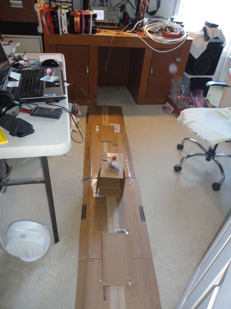
The first picture shows the timing loop. It is 1' x 8', and uses Radio Shack #278-1301, 24 AWG stranded "zip" speaker wire, with a 3' lead-in section that is still joined as a pair, and the loop formed by separating the wires and soldering them together at the “far” end of the loop (which is actually closest to the camera in this pic). The loop resonates in conjunction with a capacitor at the amplifier input. Different loop dimensions require a different capacitor (more capacitance for a smaller loop), but the value is not critical because the Q is relatively low. I taped the loop to some corrugated cardboard to hold the proper dimensions, and it folds up in the center to get it out of the way when I’m not using it.
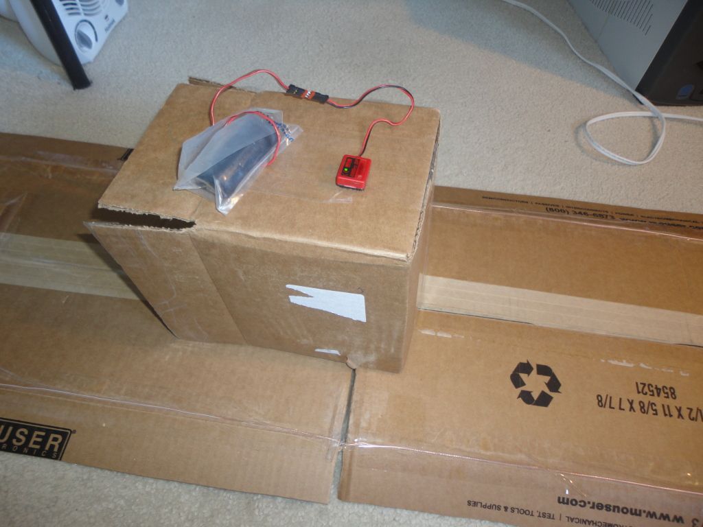
Here is an AMB transponder running from a battery, and located about 8" above the center of the timing loop.
Here’s the loop amplifier driving 25’ of 75 ohm coaxial cable. The red alligator clip is the +5V supply, which feeds the center conductor through a 75 ohm termination resistor. The scope probe is monitoring the signal output on the center conductor. As you can see, there’s not much required for the amplifier (it uses six transistors).
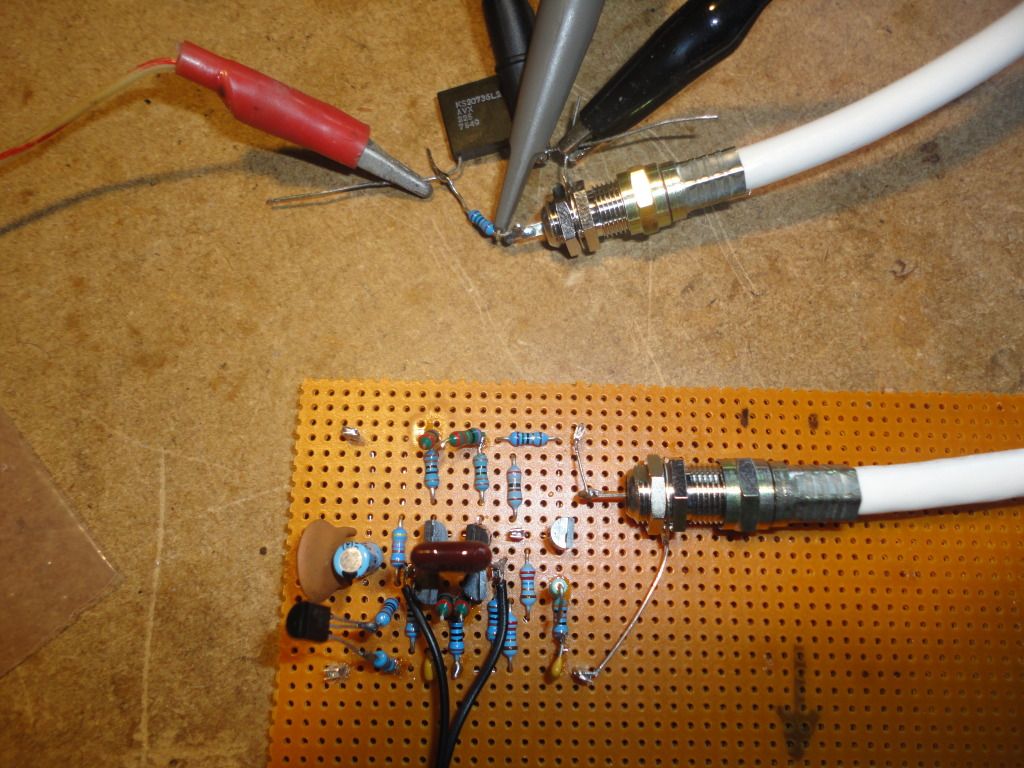
Finally, here is the output of the loop amplifier. It follows the carrier phase inversions very well.

The first picture shows the timing loop. It is 1' x 8', and uses Radio Shack #278-1301, 24 AWG stranded "zip" speaker wire, with a 3' lead-in section that is still joined as a pair, and the loop formed by separating the wires and soldering them together at the “far” end of the loop (which is actually closest to the camera in this pic). The loop resonates in conjunction with a capacitor at the amplifier input. Different loop dimensions require a different capacitor (more capacitance for a smaller loop), but the value is not critical because the Q is relatively low. I taped the loop to some corrugated cardboard to hold the proper dimensions, and it folds up in the center to get it out of the way when I’m not using it.
Here is an AMB transponder running from a battery, and located about 8" above the center of the timing loop.
Here’s the loop amplifier driving 25’ of 75 ohm coaxial cable. The red alligator clip is the +5V supply, which feeds the center conductor through a 75 ohm termination resistor. The scope probe is monitoring the signal output on the center conductor. As you can see, there’s not much required for the amplifier (it uses six transistors).
Finally, here is the output of the loop amplifier. It follows the carrier phase inversions very well.
Last edited by howardcano; 02-11-2013 at 01:19 PM. Reason: Added wire part number.
02-03-2013 | 06:34 AM
#43
Tech Regular
Joined: Aug 2005
Posts: 471
From: Taylor, MI
For AMB systems, the loop is suppose to have a resistor in the middle of the loop. It was in the RC2 Decoder instructions, so if you wanted to make your own loops. The resistor was a 470 Ohm. The loop is 1ft apart.
02-03-2013 | 06:49 AM
#44
True about the loop resistor,... But he is building the transformer. That according to AMB/MyLaps should read 100K ohms at both the loop leads and the BNC connector. Back when I got my rc decoder (as there never was an rc2) I noticed it said 1' apart.... The system20 said 2'... so I emailed AMB about it.. They replied with that was a misprint and it should be 20" - 24" apart... still have this email.
There have been a handful of threads on here about the transformer.
http://www.rctech.net/forum/electric...need-help.html
