


 78Likes
OpenStint laptiming decoder
 05-12-2026 | 11:20 PM
#61
Thread Starter
Tech Initiate
Joined: Nov 2024
Posts: 39
Hello,
I'm interested in making a decoder for a local track and have a couple questions.
Has anyone tried to make it work with an official amb loop ? The track already has a loop installed so I'd like to take advantage of it.
Would it run fine on a raspberry pi3b (not 3b+) ?
Thanks !
I'm interested in making a decoder for a local track and have a couple questions.
Has anyone tried to make it work with an official amb loop ? The track already has a loop installed so I'd like to take advantage of it.
Would it run fine on a raspberry pi3b (not 3b+) ?
Thanks !
I did not test with rpi3b. The decoding process requires both usb i/o and cpu, and b+ improved on both over model 3b. On a b3+, the cpu usage is about 40% of a single core, so I'd expect a 3b to work just as well. Note though, you can use the same host computer which runs the lap counting software. On my 1.7 ghz intel cpu from 2013, the cpu usage is less than 3%.
 05-20-2026 | 02:51 AM
#63
Thread Starter
Tech Initiate
Joined: Nov 2024
Posts: 39
V2 TRANSPONDERS TESTED AND VERIFIED
Thank you everybody for your patience. From now on, the v2 transponder is the primary version you see when visiting openstint-transponder. The previous version is available in a separate branch (v1).
Highlights:
MEASUREMENTS
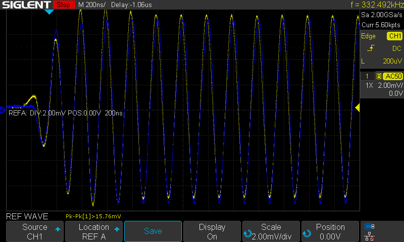
Signal strength (blue: RC4H; yellow: OpenStint v2; same distance)
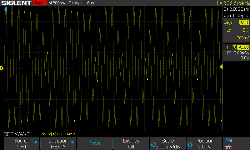
Bit transitions:
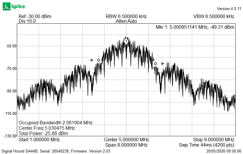
Occupied bandwith:
TRANSPONDER PANELS FOR SALE
I have now multiple panels which I'm offering for sale. Each panels are programmed and tested with the latest OpenStint firmware. 30 EUR/panel (8 pcs transponders). I'll send them as a regular, sub 50-g mail. Shipping costs are about 5 EUR when sending untracked, and 10-12 EUR when sending tracked. Contact me in PM for details.
Note: this deal works only if you need 1-2 panels; for larger quantities, go to JLCPCB.
WHAT'S NEXT?
The transmit antenna is on L2-L3, leaving the bottom layer free for a 3rd loop. I think this transponder can be smaller when the bottom layer is utilised as well. This time I'd like to get rid of the 10 panels I have before spinning a new version though.
PS. savage24x: you're good with the HF balun, the preamp is a nice-to-have. I have a single piece left from earlier prototypes, contact me in private.
Thank you everybody for your patience. From now on, the v2 transponder is the primary version you see when visiting openstint-transponder. The previous version is available in a separate branch (v1).
Highlights:
- similar signal level to an RC4Hybrid
- works down to 2.8 V supply rail
- flat signal level down to 3.4 V (miniZ and 1S-battery is support)
- much easier to tune, less harmonics, symmetric sidelobes
MEASUREMENTS
Signal strength (blue: RC4H; yellow: OpenStint v2; same distance)
Bit transitions:
Occupied bandwith:
TRANSPONDER PANELS FOR SALE
I have now multiple panels which I'm offering for sale. Each panels are programmed and tested with the latest OpenStint firmware. 30 EUR/panel (8 pcs transponders). I'll send them as a regular, sub 50-g mail. Shipping costs are about 5 EUR when sending untracked, and 10-12 EUR when sending tracked. Contact me in PM for details.
Note: this deal works only if you need 1-2 panels; for larger quantities, go to JLCPCB.
WHAT'S NEXT?
The transmit antenna is on L2-L3, leaving the bottom layer free for a 3rd loop. I think this transponder can be smaller when the bottom layer is utilised as well. This time I'd like to get rid of the 10 panels I have before spinning a new version though.
PS. savage24x: you're good with the HF balun, the preamp is a nice-to-have. I have a single piece left from earlier prototypes, contact me in private.
05-23-2026 | 01:58 PM
#64
Tech Rookie
Joined: Sep 2025
Posts: 10
From: Germany
Hi,
I am trying to understand the transponder ordering & flashing process via JLCPCB. I tried to place the order via the web user interfacel.
- Delivery Format option:
If I choose single PCB I get a error message about duplicates later after uploading bom and pos files. I could instruct to ignore it, but not sure whether that is right.
If I choose panel by customer (which also sounds about right), I am asked to enter dimensions. When I enter 2 columns 4 rows, I end up with a total cost, that is above 600 USD. Doesn't sound right either.
- What are you recommending as surface finish option?
- Flashing the firmware:
I think I can take the easy way and skip the build process and directy jump to flashing the Main.hex file from the release package using the STM32CubeProg tool linked earlier in the thread (although avrdude is mentioned in github)
However, what hardware do I need to connect to the transponder? Do I need a full Atmel ICE kit? Google returns a huge range of devices.
Thanks a lot!
05-24-2026 | 03:05 AM
#65
Tech Rookie
Joined: Oct 2005
Posts: 12
From: Glastonbury, UK
- Flashing the firmware:
I think I can take the easy way and skip the build process and directy jump to flashing the Main.hex file from the release package using the STM32CubeProg tool linked earlier in the thread (although avrdude is mentioned in github)
However, what hardware do I need to connect to the transponder? Do I need a full Atmel ICE kit? Google returns a huge range of devices.
(in fact you can make a basic updi programmer yourself using a resistor if you have another programmer lying around but it's fiddly if you haven't been around the block)
05-24-2026 | 11:20 PM
#66
Thread Starter
Tech Initiate
Joined: Nov 2024
Posts: 39
Hi,
I am trying to understand the transponder ordering & flashing process via JLCPCB. I tried to place the order via the web user interfacel.
- Delivery Format option:
If I choose single PCB I get a error message about duplicates later after uploading bom and pos files. I could instruct to ignore it, but not sure whether that is right.
If I choose panel by customer (which also sounds about right), I am asked to enter dimensions. When I enter 2 columns 4 rows, I end up with a total cost, that is above 600 USD. Doesn't sound right either.
- What are you recommending as surface finish option?
Go to the recommended release linked from the readme, and download the "panel-release.zip". Inside, there are:
- gerbers.zip: this describes the various layers for manufactoring
- bom.csv: a list of components to source for the assembly
- pos.csv: the position and orientation of the aforementioned components.
All of these files must be read by the manufacturer, you're not supposed to have anything to modify on them.
2. GO TO JLCPCB, REGISTER, AND "ORDER NOW"
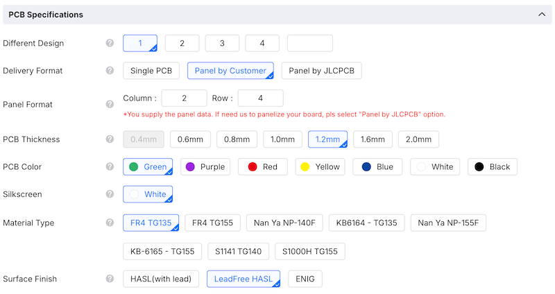
First, you have to specify the PCB parameters. Important settings are set automatically on gerber upload. You have to change:
- delivery format: panel by customer
- panel format: 2x4
- PCB Thickness: 1.2 mm (important!)
Do not change anything else. For surface finish, HASL is good enough. Lead-based soldering is easier to prototype, and compliant/legal for diy purposes. Lead-free also works (melts differently at higher temps though).
Also tick the "PCB assembly" toggle. Defaults work fine.
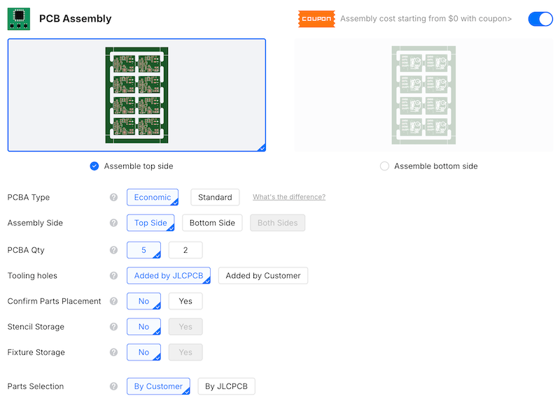
3. SPECIFY PCB
1. verify top side was selected
2. upload POS & BOM; select "complete file, ...", JLC has nothing to do
3. BOM screen: is something is out-of-stock, you'll stop here. otherwise proceed
4. Component placement: there is a dot next to all components on the silkscreen (white drawing). Verify components purple dot aligns with the white dots. The LED's negative side is towards the MCU. You can correct if something is wrong.
With lead-free specs, 5 panels:
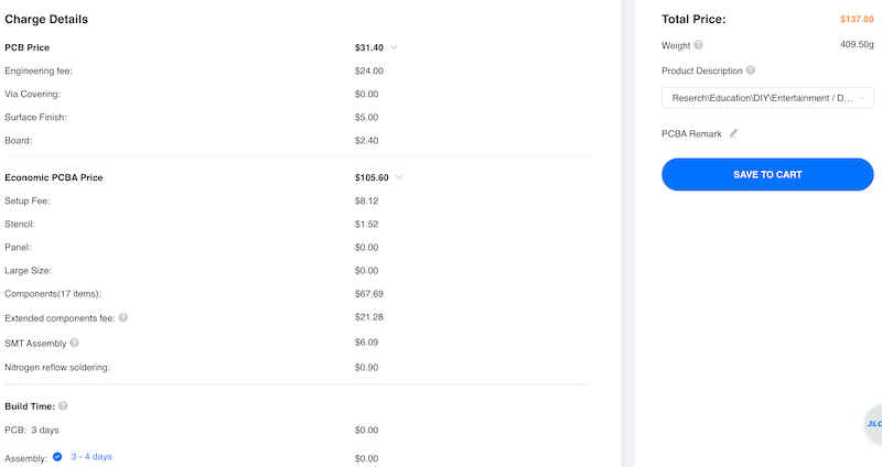
4. Save to cart, specify shipping, apply coupons, pay your taxes, etc.
05-29-2026 | 09:13 AM
#67
Tech Rookie
Joined: Apr 2017
Posts: 10
Hi,
Thanks for the work, and it's great to be able to easily order from JLCPCB. We still need to figure out how to program the ATTINY. Earlier, we mentioned the Adafruit High Voltage UPDI Friend, but I see it only has one UPDI pin, so do we just connect GND, PWR to VTG, and UPDI to UPDI?
Is there a place in the transponder code to change the number?
Thanks
05-29-2026 | 12:54 PM
#68
Thread Starter
Tech Initiate
Joined: Nov 2024
Posts: 39
Hi,
Thanks for the work, and it's great to be able to easily order from JLCPCB. We still need to figure out how to program the ATTINY. Earlier, we mentioned the Adafruit High Voltage UPDI Friend, but I see it only has one UPDI pin, so do we just connect GND, PWR to VTG, and UPDI to UPDI?
Is there a place in the transponder code to change the number?
Thanks
GND->GND
PWR->VTG
UPDI->UPDI
This scheme relies on the reverse current protection of the voltage regulator. I'm programming them this way.
(The atmel-ice does not provide power to the board, VTG is meant for Atmel-ICE to find the voltage of IO lines; I just supply +3.3V externally to VTG as well).
The transponder number is generated from the serial number of the MCU. You can override it.
06-01-2026 | 12:24 PM
#69
Tech Apprentice
Joined: Jul 2014
Posts: 53
Hello,
First, I can confirm it works on a Pi3B (not +) as you expected ! Also, it seems to work fine with an amb loop on a large outside track.
After some testing at home with the decoder, I have a weird issue with an RC4 Hybrid that is not recognized. My setup is RTL-SDRv4, Pi3B, and a shitty loop with a 1:9 balun.
I tried a MRT and 2 RC4Hybrids, and one of the hybrid is entirely not detected. The two other transponder work fine, with occasional ghost transponders detected. I checked with my usual RCHourglass decoder and the problematic hybrid works fine, signal quality is identical to the other. I tried monitor mode : no frames. I tried increasing and decreasing the gain a bit, but no improvement. Same on PC. Only the ground noise increases in the status messages when the transponder is close to the loop (otherwise around -42)
Any idea ? Undetected transponder ID is 6215277, if that can help.
Thanks !
Jean
Last edited by TeamRacing80; 06-02-2026 at 01:43 PM.
Yesterday | 12:49 AM
#70
Thread Starter
Tech Initiate
Joined: Nov 2024
Posts: 39
Please do a packet capture of both problematic transponders separately. You should have the rtl-sdr command line tools installed. Run this:
It captures 5 seconds worth of (12.5 million) samples around 5 MHz at 2.5 MSPS. You'll end up with a 25 MB file, compress it and send me for further analysis to [email protected]; Please send the output of "openstint_rtlsdr" as well (from start to the first status message).
---
I'm wondering what the problems can be...
While ghost detections are possible, they are extremely unlikely. There has to be a bit error which passes error-checking, and the same erroneous message has to appear twice to get reported as a passing. Possible, but unlikely. I think the decoder misinterprets a status message as a normal message somehow.
Transponder not detected at all: huhh... I've seen similar phenomena twice so far.
Firstly, too much gain overdrives the frontend, and symbols interleave with each other. In such conditions, preamble detection is not possible. The solution is easy (decrease the gain). There is a tutorial on finding a proper gain with SdrAngel.
Secondly, it is possible that the transponder's clock is off by a good amount. The clock source on MyLaps transponders is extremely inaccurate, and they typically drift downwards in frequency as they age. If the frequency is off by ~19 kHz, detection is not possible (you'll see the exact phenomena as you describe).
There is this line; try recompile with different values (ie. 5MHz-10kHz = 4990000), maybe it helps. @Oldfan suggested this fix long time ago anyway
rtl_sdr -f 5000000 -s 2500000 -g 20 -n 12500000 capture_rc4.iq
---
I'm wondering what the problems can be...
While ghost detections are possible, they are extremely unlikely. There has to be a bit error which passes error-checking, and the same erroneous message has to appear twice to get reported as a passing. Possible, but unlikely. I think the decoder misinterprets a status message as a normal message somehow.
Transponder not detected at all: huhh... I've seen similar phenomena twice so far.
Firstly, too much gain overdrives the frontend, and symbols interleave with each other. In such conditions, preamble detection is not possible. The solution is easy (decrease the gain). There is a tutorial on finding a proper gain with SdrAngel.
Secondly, it is possible that the transponder's clock is off by a good amount. The clock source on MyLaps transponders is extremely inaccurate, and they typically drift downwards in frequency as they age. If the frequency is off by ~19 kHz, detection is not possible (you'll see the exact phenomena as you describe).
There is this line; try recompile with different values (ie. 5MHz-10kHz = 4990000), maybe it helps. @Oldfan suggested this fix long time ago anyway
Yesterday | 11:46 AM
#71
Tech Apprentice
Joined: Jul 2014
Posts: 53
Indeed, that seems to be the reason. I used a scope to measure the frequency of both hybrid transponders, the one that works is exactly on 5MHz, the one that doesn't is closer to 5.03MHz. Also its signal is a bit distorted (looks a little bit like a sawtooth).
It's quite an old transponder, and surprisingly its frequency is on the high side rather than low, I double checked that.
I'll try the fix and try to save the signal of both working transponders The ghost transponder numbers are always the same, ie each of my two working transponder appears as 2 different IDs : its true ID, and sometimes a second "fake" ID as well.
It's quite an old transponder, and surprisingly its frequency is on the high side rather than low, I double checked that.
I'll try the fix and try to save the signal of both working transponders
The ghost transponder numbers are always the same, ie each of my two working transponder appears as 2 different IDs : its true ID, and sometimes a second "fake" ID as well.Last edited by TeamRacing80; Yesterday at 11:57 AM.
Yesterday | 01:34 PM
#72
Thread Starter
Tech Initiate
Joined: Nov 2024
Posts: 39
Huhh, a 30 kHz offset is pretty insane.
Up to this point, I discouraged everyone to play with the preamble-detector's thresholding. In your case, a less conservative value (like a fixed 0.6) can be justified. It can detect 30+ kHz offset for *some* packets (depending also on noise). If you're running in monitor mode (-m flag), it reports the guesstimated frequency offsets (FREQ .
.
I'll experiment with alternative preamble detection techniques as well.
Up to this point, I discouraged everyone to play with the preamble-detector's thresholding. In your case, a less conservative value (like a fixed 0.6) can be justified. It can detect 30+ kHz offset for *some* packets (depending also on noise). If you're running in monitor mode (-m flag), it reports the guesstimated frequency offsets (FREQ
.I'll experiment with alternative preamble detection techniques as well.
Currently Active Users Viewing This Thread: 2 (0 members and 2 guests)


