


 78Likes
OpenStint laptiming decoder
 01-28-2026 | 12:27 AM
#16
Thread Starter
Tech Initiate
Joined: Nov 2024
Posts: 39
Do you run the `integrations/bridge-zround.py`?
The OpenStint project defines its own protocol, but it's currently not supported by any other laptimers. By default, it listens on port 5556.
The ZRound is compatible with many laptimer protocols, but also defines its' own. By default, it connects to port 5001.
There is a python-based integration to convert between the two. It has to run as well, meaning there are 3 things you have to start: openstint, zround-bridge and zround manager.
There is a setup tutorial which I think is applicable on OrangePi as well.
Once I - or someone else - manages to build a P3/MyLaps bridge, we can use this decoder with LiveTime/RC-timing as well.
The OpenStint project defines its own protocol, but it's currently not supported by any other laptimers. By default, it listens on port 5556.
The ZRound is compatible with many laptimer protocols, but also defines its' own. By default, it connects to port 5001.
There is a python-based integration to convert between the two. It has to run as well, meaning there are 3 things you have to start: openstint, zround-bridge and zround manager.
OpenStint:5556 <---> zround-bridge:5001 <---> ZRound
Once I - or someone else - manages to build a P3/MyLaps bridge, we can use this decoder with LiveTime/RC-timing as well.
 02-03-2026 | 04:35 PM
#18
Tech Rookie
iTrader: (3)
Joined: Oct 2009
Posts: 18
From: W. GA
I placed an order for the transponders this past weekend from JLC. The total for 5 boards came out to a bit over $210 USD ($60 in tariff+$50 in shipping) with a $10 new user coupon for five panels on github. It appears production won't be effected by the February holidays and they'll be finished and shipped out by the end of the week.
I did get a warning the 20mhz crystal used on the board was in low supply, preventing me from ordering 10 boards. The suggested alternatives use a different footprint, HC-49S-SMD. If you broaden the search there are SMD3225-4P alternatives but the capacitance is different from the 15pf in the bom.
I did get a warning the 20mhz crystal used on the board was in low supply, preventing me from ordering 10 boards. The suggested alternatives use a different footprint, HC-49S-SMD. If you broaden the search there are SMD3225-4P alternatives but the capacitance is different from the 15pf in the bom.
Last edited by durtman; 02-10-2026 at 10:41 PM.
02-04-2026 | 12:57 AM
#19
Thread Starter
Tech Initiate
Joined: Nov 2024
Posts: 39
I placed an order for the transponders this past weekend from JLC. The total for 5 boards came out to a bit over $210 USD ($60 in tariff) with a $10 new user coupon for five panels on github. It appears production won't be effected by the February holidays and they'll be finished and shipped out by the end of the week.
2025 October (first design) - 5 panel, 40 pcs @ $130
2025 December - 5 panel, 40 pcs @ $160 (extra components were added though)
2026 February - 5 panel, 40 pcs @ $195
The price increase is quite visible. The MCU's price went up considerably for sure (~$.4x -> $.62), but I don't know what else...
I did get a warning the 20mhz crystal used on the board was in low supply, preventing me from ordering 10 boards. The suggested alternatives use a different footprint, HC-49S-SMD. If you broaden the search there are SMD3225-4P alternatives but the capacitance is different from the 15pf in the bom.
02-04-2026 | 12:58 AM
#20
Tech Initiate
Joined: May 2024
Posts: 27
From: taipei
I'm pleased that the Windows version supports RTL-SDR V4, but during testing, I encountered a very low accuracy issue when using an RCHourglass transponder.
However, dpereda doesn't have this problem (https://github.com/dpereda/openstint...rtlsdr-support).
The following information suggests that heating the ceramic oscillating crystal with a soldering iron improves the accuracy after frequency shifting.
I also experienced very low accuracy with an RCHourglass transponder using a quartz oscillating crystal, but the frequency shift rate after heating was too low to cause any change.
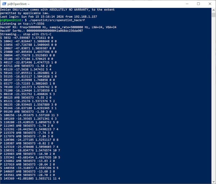
P 245427 AMB 9054415 0.07 3 0
P 245987 AMB 6170831 0.36 3 0
P 246169 AMB 9054415 -0.33 2 0
S 248093 -13.887955 0.6209385 1619 13
P 249921 AMB 5122255 -0.41 2 0
S 253196 -15.625666 0.671906 1571 11
P 252910 AMB 5122255 -0.70 2 0
P 255110 AMB 6170831 -0.80 2 0
S 258264 -14.165384 1.0111554 1549 14
S 263317 -15.54817 0.9497359 1557 11
S 268373 -13.748856 1.1199342 1550 5
P 269396 AMB 6170831 -0.71 3 0
S 273436 -15.75556 1.2064183 1565 10
S 278498 -13.823208 1.0250344 1549 3
S 283561 -15.9267235 0.998238 1555 3
S 288621 -15.964384 0.8444875 1532 2
S 293671 -13.885162 0.93904746 1554 2
S 298726 -15.904615 0.88216096 1575 170
P 298683 AMB 6170831 0.56 305 0
S 303781 -14.011459 1.0007908 1788 139
S 308843 -15.81168 1.163349 1791 704
S 313904 -15.6712 0.694628 1742 1735
S 318978 -14.380028 1.0818797 1687 1682
P 316675 AMB 6170831 0.72 4096 0
S 324032 -15.515686 0.9550401 1673 1264
S 329115 -15.628176 1.1601095 1620 0
S 334154 -15.179371 0.8359169 1610 2
P 334046 AMB 9054415 -0.20 2 0
P 334478 AMB 9054415 0.35 3 0
S 339216 -15.827322 1.096461 1580 11
S 344285 -16.06084 0.9382957 1624 565
P 343604 AMB 6170831 0.67 676 0
S 349338 -15.746948 1.0568093 1733 1396
S 354397 -15.477932 0.5965904 1703 1699
S 359450 -15.817425 1.3155696 1699 1693
S 364531 -13.960957 0.39396092 1725 1720
P 359908 AMB 6170831 0.77 4096 0
S 369607 -13.999393 0.7691634 1669 431
S 374668 -15.633345 0.9228952 1613 4
P 375896 AMB 6170831 -0.04 2 0
P 376513 AMB 9054415 -0.39 3 0
P 378627 AMB 6170831 -0.54 2 0
P 378867 AMB 9054415 -0.28 2 0
However, dpereda doesn't have this problem (https://github.com/dpereda/openstint...rtlsdr-support).
The following information suggests that heating the ceramic oscillating crystal with a soldering iron improves the accuracy after frequency shifting.
I also experienced very low accuracy with an RCHourglass transponder using a quartz oscillating crystal, but the frequency shift rate after heating was too low to cause any change.
P 245427 AMB 9054415 0.07 3 0
P 245987 AMB 6170831 0.36 3 0
P 246169 AMB 9054415 -0.33 2 0
S 248093 -13.887955 0.6209385 1619 13
P 249921 AMB 5122255 -0.41 2 0
S 253196 -15.625666 0.671906 1571 11
P 252910 AMB 5122255 -0.70 2 0
P 255110 AMB 6170831 -0.80 2 0
S 258264 -14.165384 1.0111554 1549 14
S 263317 -15.54817 0.9497359 1557 11
S 268373 -13.748856 1.1199342 1550 5
P 269396 AMB 6170831 -0.71 3 0
S 273436 -15.75556 1.2064183 1565 10
S 278498 -13.823208 1.0250344 1549 3
S 283561 -15.9267235 0.998238 1555 3
S 288621 -15.964384 0.8444875 1532 2
S 293671 -13.885162 0.93904746 1554 2
S 298726 -15.904615 0.88216096 1575 170
P 298683 AMB 6170831 0.56 305 0
S 303781 -14.011459 1.0007908 1788 139
S 308843 -15.81168 1.163349 1791 704
S 313904 -15.6712 0.694628 1742 1735
S 318978 -14.380028 1.0818797 1687 1682
P 316675 AMB 6170831 0.72 4096 0
S 324032 -15.515686 0.9550401 1673 1264
S 329115 -15.628176 1.1601095 1620 0
S 334154 -15.179371 0.8359169 1610 2
P 334046 AMB 9054415 -0.20 2 0
P 334478 AMB 9054415 0.35 3 0
S 339216 -15.827322 1.096461 1580 11
S 344285 -16.06084 0.9382957 1624 565
P 343604 AMB 6170831 0.67 676 0
S 349338 -15.746948 1.0568093 1733 1396
S 354397 -15.477932 0.5965904 1703 1699
S 359450 -15.817425 1.3155696 1699 1693
S 364531 -13.960957 0.39396092 1725 1720
P 359908 AMB 6170831 0.77 4096 0
S 369607 -13.999393 0.7691634 1669 431
S 374668 -15.633345 0.9228952 1613 4
P 375896 AMB 6170831 -0.04 2 0
P 376513 AMB 9054415 -0.39 3 0
P 378627 AMB 6170831 -0.54 2 0
P 378867 AMB 9054415 -0.28 2 0
02-04-2026 | 02:51 AM
#21
Thread Starter
Tech Initiate
Joined: Nov 2024
Posts: 39
I have multiple good news about this project.
RTL-SDR v4 SUPPORT
Our forum member, @danny325is, added support for RTL-SDR some weeks ago, and is now merged with the rest of the improvements. As RTL-SDR v4 is an inexpensive, ~$40 device, the barrier of entry was lowered significantly. For purchasing options, see their official site, there are multiple options (Amazon/Ebay/AliExpress). Make sure you buy the v4 version, as the decoder was not tested with earlier versions (I just ordered an older one, weeks to arrive).
WINDOWS BUILD
The project is built for Windows semi-automatically, meaning you can download a .zip, containing the whole project (no installer is needed). You no longer have to install python to use the core integrations, as the zround and p3 bridges are compiled to their own .exe files (each of such file contain the whole python runtime and dependencies, hence the 10 MB+ filesize). As such, once you have the SDR drivers installed:
1. plug in the radio to an USB port
2. double-click on openstint_hackrf.exe or openstint_rtlsdr.exe (and ignore the "untrusted code" warnings - it's not signed, hence the error)
3. double-click on bridge-zround.exe
4. start your ZRound, and set 127.0.0.1 as decoder ip address
You might have to allow the firewall exceptions meanwhile.
INCREASED RECEPTION QUALITY
Firstly, the symbol synchronizer was fixed. Previously about 8-10% of all frames were dropped. With the fixed version, I was able to lower the preamble-detection threshold while still maintaining a very high detection ratio. Long story short, we can detect and decode weaker signals more reliably now.
Secondly, a feature called "adaptive equalisation" was added. For super-nerds only: the transmit coils, the antenna and the whole transmit-receive chain has non-idealities, resulting in bit errors. An adaptive equaliser learns these errors and corrects for them. A few cars have to pass, and the system tunes itself.
The result of these two improvements, more frames are decoded even in non-ideal radio environments. In ideal ones, EVM figures lower that 0.05 are often observable (rssi > -10 dB; hackrf one).
RELIABLE PASSING TIME DETECTION
The "point of passing" was determined previously as "point of highest signal strength". Now there is a more sophisticated algorithm implemented.
I placed two transponders ~15 mm distance from each other. The new algorithm is reliably able to distinguish if the car passes the loop forward or reverse, based on which transponder passes first (tested at low speeds).
EDIT: the p3-bridge feature was removed; contact in private message if you really need it.
Last edited by zsellera; 02-08-2026 at 12:51 PM. Reason: out of precaution, the p3-bridge feature was removed (contact in pm for details)
02-04-2026 | 03:25 AM
#22
Thread Starter
Tech Initiate
Joined: Nov 2024
Posts: 39
I'm pleased that the Windows version supports RTL-SDR V4, but during testing, I encountered a very low accuracy issue when using an RCHourglass transponder.
However, dpereda doesn't have this problem (https://github.com/dpereda/openstint...rtlsdr-support).
The following information suggests that heating the ceramic oscillating crystal with a soldering iron improves the accuracy after frequency shifting.
I also experienced very low accuracy with an RCHourglass transponder using a quartz oscillating crystal, but the frequency shift rate after heating was too low to cause any change.
P 245987 AMB 6170831 0.36 3 0
P 246169 AMB 9054415 -0.33 2 0
S 248093 -13.887955 0.6209385 1619 13
However, I'd look for the problem elsewhere in your case.
1. Too much noise or amplifications
The "-13.88 dBFS" noise floor measurement is really off. it should be lower than -39.0 ideally. It can be caused by too much gain. During testing, I settled around "-g 20" for rtl-sdr; "-g 30" max.
The "0.36 dBFS" and "-0.33 dBFS" indicates the signal you received is clipping. "0 dBFS" means the signal is using the full range of the ADC. As the signal is sinusoid, there is a difference between "peak" and "rms", this value can be over 0.0 - but it shouldn't. It should be max "-3.0" imho.
2. Crystal fails to start / MCU falls back to internal oscillator
The initial symbol sync happens on the first 12 bits of the preamble, and there are about 100 bits in total. For a 90* phase shift (so decoding fails), the frequency has to differ by more than 600 ppm. My first Casio hand watch - a used from the '80s - was advertised as "max 1 second per day", which is 12 ppm. While 40+ years passed, I'd expect this level accuracy from a cheap XO today. There are orders of magnitude in difference... I guess the MCU failed to start the crystal, and fall back to some internal oscillator: when you heat the crystal, the microcontroller's temperature is changing as well.
3. You are also right
I indeed did removed a makeshift costas loop when I fixed the symbol synchronizer. There is no good reason for the removal, I'll add it back in the coming weekend or so (I simply did not take into account the "failed crystal" case above). It can compensate for 1000+ ppm of clock differences.
Last edited by zsellera; 02-04-2026 at 03:30 AM. Reason: typo
02-13-2026 | 03:19 AM
#24
Tech Rookie
iTrader: (3)
Joined: Oct 2009
Posts: 18
From: W. GA
https://github.com/zsellera/openstin...er-protocol.md
03-02-2026 | 07:01 PM
#25
Tech Rookie
iTrader: (3)
Joined: Oct 2009
Posts: 18
From: W. GA
I've had success with the Thin client running OpenStint and detecting my MRT ptx with the Hackrf one and near field probe connected. I'm able to connect it to Zround on my win10 pc, still need to build a loop. Similar success with the windows executables. I got a bit distracted for the last couple weeks using the Hackrf on my windows PC to mess around with tuning into radio stations during my free time.
Unfortunately with linux and command line I'm way over my head. I did a new install of ubuntu. I was initially not able to get the openstint.service to work, after a few hours of shots in the dark, I finally used nano to view "openstint.service" and realized I needed to edit it to point to openstint_hackrf and got the service to start up on boot with the hackrf connected. I have bridge-zround.service starting on boot as well.
After looking through the process to flash the transponders, I'm lost. So far, I've copied the transponder git, and ran cmake in the firmware directory.
Originally Posted by Openstint-Transponder
cmake -DCMAKE_BUILD_TYPE=Release .
make
make
Originally Posted by UbuntuThinClient
pi@ostc:~/osptx$
...
-- Build files have been written to: /home/pi/osptx/firmware
pi@ostc:~/osptx/firmware$ make
[ 9%] Generating C011F4.ld
[ 9%] Built target CMSIS_LD_C011F4
[ 18%] Building C object CMakeFiles/transponder.dir/main.c.obj
cc: warning: ‘-mcpu=’ is deprecated; use ‘-mtune=’ or ‘-march=’ instead
cc: fatal error: cannot read spec file ‘nosys.specs’: No such file or directory
compilation terminated.
make[2]: *** [CMakeFiles/transponder.dir/build.make:76: CMakeFiles/transponder.dir/main.c.obj] Error 1
make[1]: *** [CMakeFiles/Makefile2:436: CMakeFiles/transponder.dir/all] Error 2
make: *** [Makefile:91: all] Error 2
pi@ostc:~/osptx/firmware$
Originally Posted by UbuntuThinClient
pi@ostc:~/osptx/firmware$ st-flash --connect-under-reset --format ihex write transponder.hex
st-flash 1.8.0
2026-03-02T06:46:57 WARN common.c: NRST is not connected
2026-03-02T06:46:57 ERROR common.c: Soft reset failed: error write to AIRCR
Failed to enter SWD mode
Failed to connect to target
Failed to parse flash type or unrecognized flash type
st-flash 1.8.0
2026-03-02T06:46:57 WARN common.c: NRST is not connected
2026-03-02T06:46:57 ERROR common.c: Soft reset failed: error write to AIRCR
Failed to enter SWD mode
Failed to connect to target
Failed to parse flash type or unrecognized flash type
03-02-2026 | 11:58 PM
#26
Thread Starter
Tech Initiate
Joined: Nov 2024
Posts: 39
This is the DIY programming header I use, and the reason there is no "programming JIG" yet:

Aliexpress links:
pogo pins: [1] [2] [3]
pin header: [4] (2 mm pitch is a less common item, but I had no space on board for 2.54 mm spacing)
UV curable resin: local model shop, beauty shop or [5]
cables: [6] (female-female both ends; remove plastic socket on one end to fit the pogo pins inside)
An en-mass programming requires the pogo pins. The rest is optional.
I use the UV-curable resin to secure the cables to the transponder as well (put some over the solder joints).
PROGRAMMING
Try tools with GUI, like Stm32CubeProg. Here is a precompiled hex, so you don't have to compile it.
The programming points are labeled on the silkscreen, note "CLK" is "SWCLK" and "DIO" is "SWDIO".
SIMPLEST DECODER SETUP
You can use everything from a single Windows machine (decoder + bridge + zround), no need for Raspberry or thin-client:
https://github.com/zsellera/openstin...ial-windows.md
CLOSING THOUGHTS
I know you have more questions than answers here; I'll answer them later when I have more time. I hope this helps already.
03-04-2026 | 11:48 PM
#27
Tech Rookie
iTrader: (3)
Joined: Oct 2009
Posts: 18
From: W. GA
With your help I was able to narrow down the CC error. I had to install the Arm embedded toolchain.
I then had to edit the CMakeCache.txt to point to the correct compiler directory.
Fortunately I now have this when I run make.
This has been a great motivation to spend more time with linux. I got a pair of thin clients from my work for free and use one to run firefox on linux mint connected to my TV to watch streaming sites with uBlock origin adb. The specific one I'm using is an HP T530, 1.5ghz amd processor, 4gb ram and a tiny 8gb ssd. They can be found on ebay for ~35 USD, just be sure it has a wifi card installed.
Code:
sudo apt install gcc-arm-none-eabi binutils-arm-none-eabi
Originally Posted by CMakeCache.txt
cd to the firmware directory
nano CMakeCache.txt and search for
CMAKE_C_COMPILER:FILEPATH=/usr/bin/cc
changed to
CMAKE_C_COMPILER:FILEPATH=/usr/bin/arm-none-eabi-gcc-ar
nano CMakeCache.txt and search for
CMAKE_C_COMPILER:FILEPATH=/usr/bin/cc
changed to
CMAKE_C_COMPILER:FILEPATH=/usr/bin/arm-none-eabi-gcc-ar
Originally Posted by OpenStintThinClient
Generating ihex file transponder.hex
[ 90%] Built target transponder
[100%] Target Sizes:
text data bss dec hex filename
5984 312 2500 8796 225c /home/pi/osptx/firmware/transponder.elf
[100%] Built target transponder_always_display_size
pi@ostc:~/osptx/firmware$ ls
build cmake CMakeFiles CMakeLists.txt main.c transponder.elf
C011F4.ld CMakeCache.txt cmake_install.cmake _deps Makefile transponder.hex
03-08-2026 | 12:55 PM
#28
Tech Rookie
iTrader: (3)
Joined: Oct 2009
Posts: 18
From: W. GA
Here's a 3d printable jig to hold your transponder securely while programming it. I've got enough spare pogo pins to mail a few out for anyone whose thinking of getting some transponders. If you don't have access to a 3d printer, I'll be happy to send a print as well to those who have bought transponders.

Available at https://www.thingiverse.com/thing:7310937
..
I got a pair of OS transponders showing up in OpenStint with the firmware you provided. I initially flashed the hex I created but despite getting flashing light when powering it up, don't get any hits with the hackrf. I'll need to spend some time to figure out my mistake, but I have an idea.
03-09-2026 | 06:55 AM
#29
Thread Starter
Tech Initiate
Joined: Nov 2024
Posts: 39
Thanks, it looks cool!
It's a known phenomena. The transmission is timing-critical, and the firmware is using the SPI bus to do it. The next bit has to be available right when the transmit buffer goes empty. You have to compile with optimalization, otherwise the compiler keeps extra operations in the loop (to help debugging).
I got a pair of OS transponders showing up in OpenStint with the firmware you provided. I initially flashed the hex I created but despite getting flashing light when powering it up, don't get any hits with the hackrf. I'll need to spend some time to figure out my mistake, but I have an idea.
It's a known phenomena. The transmission is timing-critical, and the firmware is using the SPI bus to do it. The next bit has to be available right when the transmit buffer goes empty. You have to compile with optimalization, otherwise the compiler keeps extra operations in the loop (to help debugging).
03-23-2026 | 02:19 AM
#30
Thread Starter
Tech Initiate
Joined: Nov 2024
Posts: 39
RC4 SUPPORT - HELP NEEDED
@Oldfan suggested and implemented a scheme to learn RC4 messages, similarly to how RCHourGlass does this. Before committing to further work, I'd like to verify that the scheme indeed works.
First off, RC4 was designed to make reverse-engineering hard, and we do not pursue it neither. It sends many different unique messages, probably sending a random sequence (IV) in each message, then obfuscated with a block-cipher (I would have implemented it in a similar way myself).
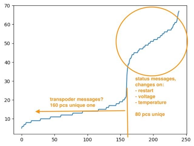
I have access to a single RC4-hybrid transponder. Based on that, the RC4 messages are 3-modal (3 distinct types and repetition rates):
Histogram:
HELP VERIFY THE UNIQENESS OF THESE MESSAGES
The best doing it on a Windows laptop, there is a special build for it.

PLEASE COLLECT DATA FROM AS MANY TRANSPONDERS AS YOU CAN, AND EMAIL THE FILES TO ME
My email address: [email protected]
The files are a few kB in size, and contain the repeating messages of a 8196 sample, in a human-readable way.
This experiment is important, as it dictates how future support around this feature is done. I'd like to collect data from at least 30 transponders.
@Oldfan suggested and implemented a scheme to learn RC4 messages, similarly to how RCHourGlass does this. Before committing to further work, I'd like to verify that the scheme indeed works.
First off, RC4 was designed to make reverse-engineering hard, and we do not pursue it neither. It sends many different unique messages, probably sending a random sequence (IV) in each message, then obfuscated with a block-cipher (I would have implemented it in a similar way myself).
I have access to a single RC4-hybrid transponder. Based on that, the RC4 messages are 3-modal (3 distinct types and repetition rates):
- The most frequent messages contain (?) voltage and temperature information. There is exactly 80 different unique messages of them at a time, and they keep changing as voltage and temperature fluctuates. A power-cycle clears them, and a new set of 80 messages is sent. As such, it makes no sense to build a memory based on these.
- There is a long-tail of messages that do not repeat within a reasonable timeframe. One can listen for hours to detect a repetition. Again, building a memory on these is not practical.
- There are 160 pcs of unique messages, accounting for ~25% of all messages detected, which do not change and do survive power-cycles. It makes sense to build a memory on these.
Histogram:
HELP VERIFY THE UNIQENESS OF THESE MESSAGES
The best doing it on a Windows laptop, there is a special build for it.
- Place the transponder near the loop, and keep it stable (simulate a car parked on the loop). The decoder switches into "Learning mode", and is indicated by a message "L 9042 START". If you change the position of the transponder, the learning mode is interruped ("L 13984 INTERRUPTED"), so keep it stable.
- After a while (RC4Hybrid: 20-25 sec, RC4 probably half the time) the decoder reads enough messages to finish learning ("L 70192 DONE 1001 320"). A "<transponder_id>.rc4" file is placed into the directory you started the program from. RC4Hybrids can read the transponder id, while regular RC4 follow a scheme of "1001.rc4", "1002.rc4", etc. You can rename these files to the actual transponder id, the program automatically reloads the changed files.
PLEASE COLLECT DATA FROM AS MANY TRANSPONDERS AS YOU CAN, AND EMAIL THE FILES TO ME
My email address: [email protected]
The files are a few kB in size, and contain the repeating messages of a 8196 sample, in a human-readable way.
This experiment is important, as it dictates how future support around this feature is done. I'd like to collect data from at least 30 transponders.
- If there is no repetition (the messages are unique), I'll call it a day and ship the feature.
- If there is repetition, I'll do some math. If there is a chance larger than 50% of having a "collision" in a random set of 8, I simply do not want to waste time on this (put what we have now behind an option flag).
- Otherwise something inbetween.

