


 1Likes
Advanced sensor tester.
 02-25-2020 | 12:26 PM
#1
Thread Starter
Tech Lord

Joined: Aug 2007
Posts: 14,052
From: Holland
2 months ago I had a talk with some clubmembers about running brushless in the rain. The sensors are a weak point, when they do become wet it will mess up the speedcontrol and basically running sensorless is not an option. Peoplle try to make it all waterproof with the chance water will still reach the sensors.
Several years ago when develloping the FDR meter it became clear what kind of sensors are used and had a solution in my mind by only modifying the sensor cable. I did throw it in the group and was ordered to make some cables. To be sure it will work with all motors because of the different sensors I needed a test tool so I quickly made one.
The basic is using 3 simple LED's switched by high impedance FET's so the LED has no influence on the sensor signal. And with that each sensor has its own voltmeter that will show the voltage level of the signal which I need to see if the sensor can handle the modification.
It took a few late evening hours to make, due handwork with a dremel not the nicest but very functional.
The box
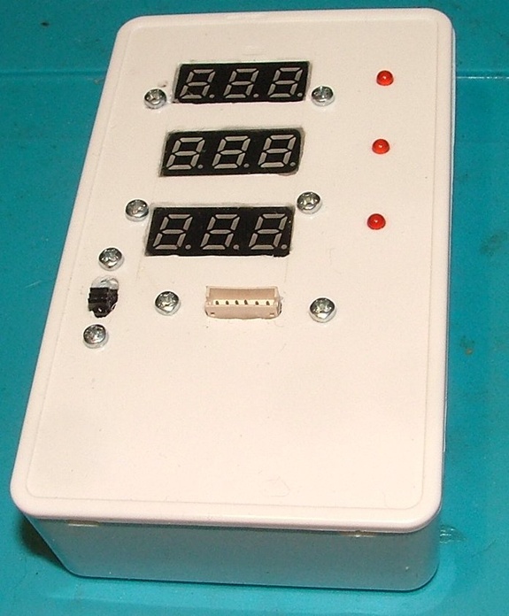
Switched on:

With motor attached


Several years ago when develloping the FDR meter it became clear what kind of sensors are used and had a solution in my mind by only modifying the sensor cable. I did throw it in the group and was ordered to make some cables. To be sure it will work with all motors because of the different sensors I needed a test tool so I quickly made one.
The basic is using 3 simple LED's switched by high impedance FET's so the LED has no influence on the sensor signal. And with that each sensor has its own voltmeter that will show the voltage level of the signal which I need to see if the sensor can handle the modification.
It took a few late evening hours to make, due handwork with a dremel not the nicest but very functional.
The box
Switched on:
With motor attached
 02-26-2020 | 12:24 AM
#2
Tech Master
Joined: Nov 2002
Posts: 1,099
From: Parts Unkown
Hi Roelof,
Looking very nice. Great job.
Can you explain what the numbers showing actually are?
Degrees timing? Anything else? Sensor quality?
If you would make the mods to the cable an internal (inside the box mod) then could you also check the cable quality in the car?
Thanks mate
Looking very nice. Great job.
Can you explain what the numbers showing actually are?
Degrees timing? Anything else? Sensor quality?
If you would make the mods to the cable an internal (inside the box mod) then could you also check the cable quality in the car?
Thanks mate
02-26-2020 | 01:05 AM
#3
Thread Starter
Tech Lord
Joined: Aug 2007
Posts: 14,052
From: Holland
These are just simpe cheap voltmeters. The sensors are powered by a 5 volt power suply. When a sensor goes bad it will not switch to close 0v and 5v
https://www.dx.com/p/mini-dc-0100v-3...l#.XlY0tPTvKUk
https://www.dx.com/p/mini-dc-0100v-3...l#.XlY0tPTvKUk
 02-26-2020 | 07:45 AM
#5
Thread Starter
Tech Lord
Joined: Aug 2007
Posts: 14,052
From: Holland
These guys run F1 in the rain, so 2wd.
With 2wd on a slippery track you want maximum control and no cogging what sensorless will do. Problem with sensors is that most of them have an internal pull up resistor of 10kohm, a drop of water on the sensor making a resistance between the output and ground will lower the output voltage because the high value pull up.
In the sensor cable are now on each sensor signal 390 ohm pull up resistors mounted making the whole signal less sensitive for the electric resistance of the water. With that a current will flow of 12mA which most sensors can handle but there are so many sensors with also a much lower output current specification that it is wise to check before even try.
And it will help any sensor brushless setup to drive error less in the rain.
02-26-2020 | 12:55 PM
#6
Tech Adept
Joined: Dec 2016
Posts: 192
From: Olathe, KS
As gigaplex said, you can conformal coat the sensor board to protect the sensors from water getting on the board. I would get the brush on style to avoid getting any in the connector. All Castle motors come with conformal coating on the sensor board, but we don't make a 21.5 turn 2 pole motor.
The connector for the sensor wire is also an issue for water because the gap between the pins can lose connection when wet. A lot of crawler guys pack the plug with dielectric grease. I've seen motors run submerged in a stream and not lose sensors when treated this way. You want to pack both the connector on the motor and the connector on the ESC. Also make sure you ESC is waterproof because it is more likely to get damaged from a few drops of water.
The connector for the sensor wire is also an issue for water because the gap between the pins can lose connection when wet. A lot of crawler guys pack the plug with dielectric grease. I've seen motors run submerged in a stream and not lose sensors when treated this way. You want to pack both the connector on the motor and the connector on the ESC. Also make sure you ESC is waterproof because it is more likely to get damaged from a few drops of water.
Currently Active Users Viewing This Thread: 1 (0 members and 1 guests)
