


 8Likes
A-B-C to C-B-A phase crossing
 12-02-2019 | 05:21 AM
#1
Thread Starter
Tech Adept
Joined: Dec 2010
Posts: 215
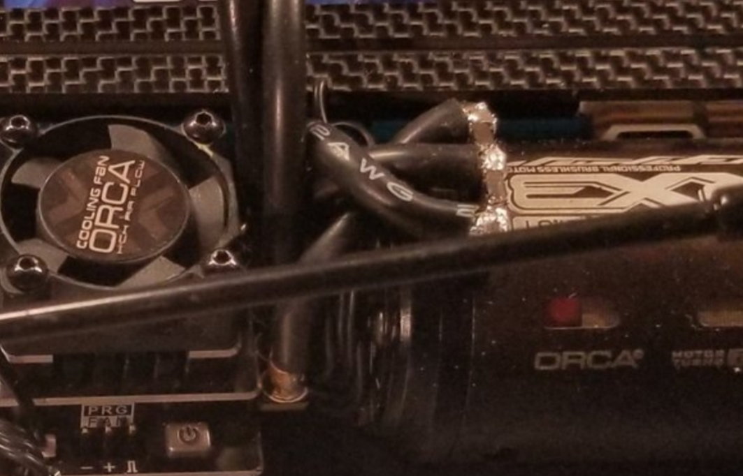
Hi guys, I've got a technical question: due to clean cable routing, I had to cross the phases from the esc to motor.
From esc phase A the wire went to motor phase C, B went to B, and C went to A. At the same time I crossed the wires in the sensor cable following the same logic.
Can you please explain me why the motor didn't work in such configuration? Isn't the same for the esc logic? Just the rotation would be inverted... I think...
I attach a picture, which is not mine, to explain the problem of cable routing I would like to avoid
*** to be more clear the picture refers to normal phase connection. Inverting the phases would allow the wires to run straight
 12-02-2019 | 05:53 AM
#2

Hi guys, I've got a technical question: due to clean cable routing, I had to cross the phases from the esc to motor.
From esc phase A the wire went to motor phase C, B went to B, and C went to A. At the same time I crossed the wires in the sensor cable following the same logic.
Can you please explain me why the motor didn't work in such configuration? Isn't the same for the esc logic? Just the rotation would be inverted... I think...
I attach a picture, which is not mine, to explain the problem of cable routing I would like to avoid
*** to be more clear the picture refers to normal phase connection. Inverting the phases would allow the wires to run straight
The latest R1/Graupner ESCs will let you swap the order of ABC to CBA with a firmware setting, but otherwise swapping the wire order on sensored motors is unsupported.
12-02-2019 | 11:28 AM
#6
12-02-2019 | 01:46 PM
#7
Thread Starter
Tech Adept
Joined: Dec 2010
Posts: 215
12-02-2019 | 01:50 PM
#9
Thread Starter
Tech Adept
Joined: Dec 2010
Posts: 215
Without seeing your handiwork the first suggestion would be that you wired the sensor cable incorrectly. But even if you got it working, this is a terrible idea. The motor wouldn't run properly due to the timing advance now being in the wrong direction, plus the vehicle will be driving the wrong way.
The latest R1/Graupner ESCs will let you swap the order of ABC to CBA with a firmware setting, but otherwise swapping the wire order on sensored motors is unsupported.
The latest R1/Graupner ESCs will let you swap the order of ABC to CBA with a firmware setting, but otherwise swapping the wire order on sensored motors is unsupported.
12-02-2019 | 02:29 PM
#10
The sensor board is rotated a certain number of degrees to advance the timing. The direction it is rotated is important, if you reverse the motor it'll be moving the timing in the opposite direction. Swapping the sensor wire around would only give the same result if there was zero timing on the motor.
12-02-2019 | 02:59 PM
#12
Thread Starter
Tech Adept
Joined: Dec 2010
Posts: 215
The sensor board is rotated a certain number of degrees to advance the timing. The direction it is rotated is important, if you reverse the motor it'll be moving the timing in the opposite direction. Swapping the sensor wire around would only give the same result if there was zero timing on the motor.
12-02-2019 | 03:01 PM
#13
Thread Starter
Tech Adept
Joined: Dec 2010
Posts: 215
the application I'm asking all this for is a pan car 235mm where the esc and motor will be mounted both on the rear pod, mounted back to back. So wires must be short and straight to do a clean job.
12-02-2019 | 03:59 PM
#14
but normally you can chose to run the motor CW or CCW... the sensor board is just that, sensors... if you set let's say 40� of mechanical timing the esc will then sum or subtract that amount accordingly to the sense of rotation previously declared in the settings... at least I understood it worked like that
12-02-2019 | 07:54 PM
#15
Actually the ESC would have to add a lot of advance. You didn't mention what motor you have. But let's assume the minimum mechanical timing on the motor is 30 degrees. Running in reverse that's now 30 degrees of retardation not advance. So if you wanted 40 or 50 degrees of total advance, the ESC would have to add 70-80 degrees. I'm not aware of any ESC that will provide that much because it's completely outside the bounds of "normal".
You might be able to modify your sensor board to physically rotate it in the other direction, which when you're running in reverse would be adding advance. Some sensor boards just have tabs that control the range.
But, you'd be much better off finding an ESC that has the ABC posts in CBA order. My Tekin RS's have the C on the left which would make it really easy to wire as you want.