


 2Likes
Gauss Meter

 11-18-2019 | 06:39 PM
#4
Tech Initiate
Joined: May 2019
Posts: 38
From: Krak�w, Poland
11-18-2019 | 07:47 PM
#5
The Fantom Facts Machine is the defacto standard. https://www.fantomracing.com/proddet...?prod=FAN28500
11-19-2019 | 03:00 AM
#6
Tech Lord

Joined: Aug 2007
Posts: 14,052
From: Holland
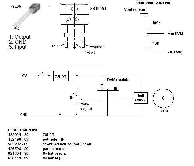
The schematik is just too simple but it works. The panel meter is a 200mV meter with a balanced input (no GND connection) if you can not find one then you have to use an isolated DC/DC converter only to power the meter. from the same power source.
The sensor set 0 Gaus at half voltage and puts out an analog voltage up or down depending the polarisation and strength of the magnet.
No real Gaus scale but I did set the distance of the sensor so it is arround half the readout (1000), from there with other rotors you can compare the strength. You can always use a simple multimeter as well
The potmeter is just to set a zero reading before placing the rotor,
11-19-2019 | 10:16 AM
#7
Joined: Mar 2011
Posts: 6,410
From: Austin,TX
I have been using this one for about 6 months and it has been doing a good job for me, ideal for 540 size rotors, the larger 4-pole 1/8 rotors are too powerful magnets and will max out to not get readings on 1/8 rotors:
11-19-2019 | 07:19 PM
#10
Magnetic field measurement is very sensitive to distance, as it drops off rapidly as distance increases. You have to have some method of positioning the rotor the exact distance every time to make accurate readings. I made this one by 3d printing a case and way to hold the rotor. It uses a hall effect sensor with an Arduino. I can't compare my readings to what others have reported because there's no calibration or standard of rotor measurement. But I can compare my own rotors. I found out why one of my 17.5s wasn't as fast as I would have expected...it had a very weak rotor.
11-20-2019 | 12:42 PM
#11
Yeah wanting to do the same - just relative measurements between motors and track magnet strength.
Yeah I am putting an order in. I have a left over arduino and was thinking the same but just running off the computer. Was a little concerned about the 0-5V measurement being to wide to get repeatable output readings at the 0-200mV range but it looks like you have it worked out. The panel meter solution is a little more pricey too but looking for a project to do with my kids so with he rest of the parts its still about $40. I have a 3d printer as well so always looking for something to make with it!
Roelof - for a panel meter the product you used isnt readily available here in the states. I was going to use this one (200mV range in 5 volt as it seems to work better to avoid current in the ground). Interested in your thoughts as although I play around with DC circuits and know some of the basics I am far from an expert on sensor monitoring.
https://www.mouser.com/datasheet/2/281/20lcd-41581.pdf
11-20-2019 | 01:39 PM
#12
Tech Lord
Joined: Aug 2007
Posts: 14,052
From: Holland
From what I see the meter has a balanced input so no GND input that directly is connected to the battery GND. That is good!
If you want to be sure you can power the meter through an isolated DC/DC converter
https://nl.mouser.com/Power/DC-DC-Co...ters/_/N-brwkv
I did start an updated version but never finished it, maybe a good next winter project.

Using opamps and an isolated DC/DC converter I think to get some better readings. I have seen differences between north and south poles, that could be caused by small loads on the potmeter and gauge sensor.
The DC/DC convrer will power the meter w/o any unwanted high resistance connection to the inputs of the meter. With this construction you can use any meter with or without a balanced input as long it can measure positive and negative voltages.
If you want to be sure you can power the meter through an isolated DC/DC converter
https://nl.mouser.com/Power/DC-DC-Co...ters/_/N-brwkv
I did start an updated version but never finished it, maybe a good next winter project.
Using opamps and an isolated DC/DC converter I think to get some better readings. I have seen differences between north and south poles, that could be caused by small loads on the potmeter and gauge sensor.
The DC/DC convrer will power the meter w/o any unwanted high resistance connection to the inputs of the meter. With this construction you can use any meter with or without a balanced input as long it can measure positive and negative voltages.
11-20-2019 | 05:51 PM
#13
For mine I used an Arduino Uno, 16x2 LCD display, a non-latching analog hall effect sensor and push button. Used the 5v power supply that came with my Arduino development kit. Total cost was ~$20. The code is super simple as you're just reading the voltage off the sensor on an analog pin. The key is getting the distance correct so you get the widest range of readings without going over the sensor's limit with some buffer since I wasn't sure if my rotors were the strongest that will be ever manufactured.
PM me if you want a copy of my Arduino code.
PM me if you want a copy of my Arduino code.
11-20-2019 | 08:02 PM
#14
Tech Master
Joined: Jul 2018
Posts: 1,011
From: Florida
The magneto pot is a resistor array with ferrite powder. The stronger the field the more powder that bridges the resistor array values. Probably pretty good for relative measurements and simplicity. Or I can send you my moms old tv. Still has a rainbow in the middle of it.