


 142Likes
Icharger x6 Mini 30A Discharge
 03-02-2022, 01:17 PM
#511
Tech Addict
iTrader: (24)
I was able to get my 1S discharge bank up and working. Thanks for everyone's assistance.
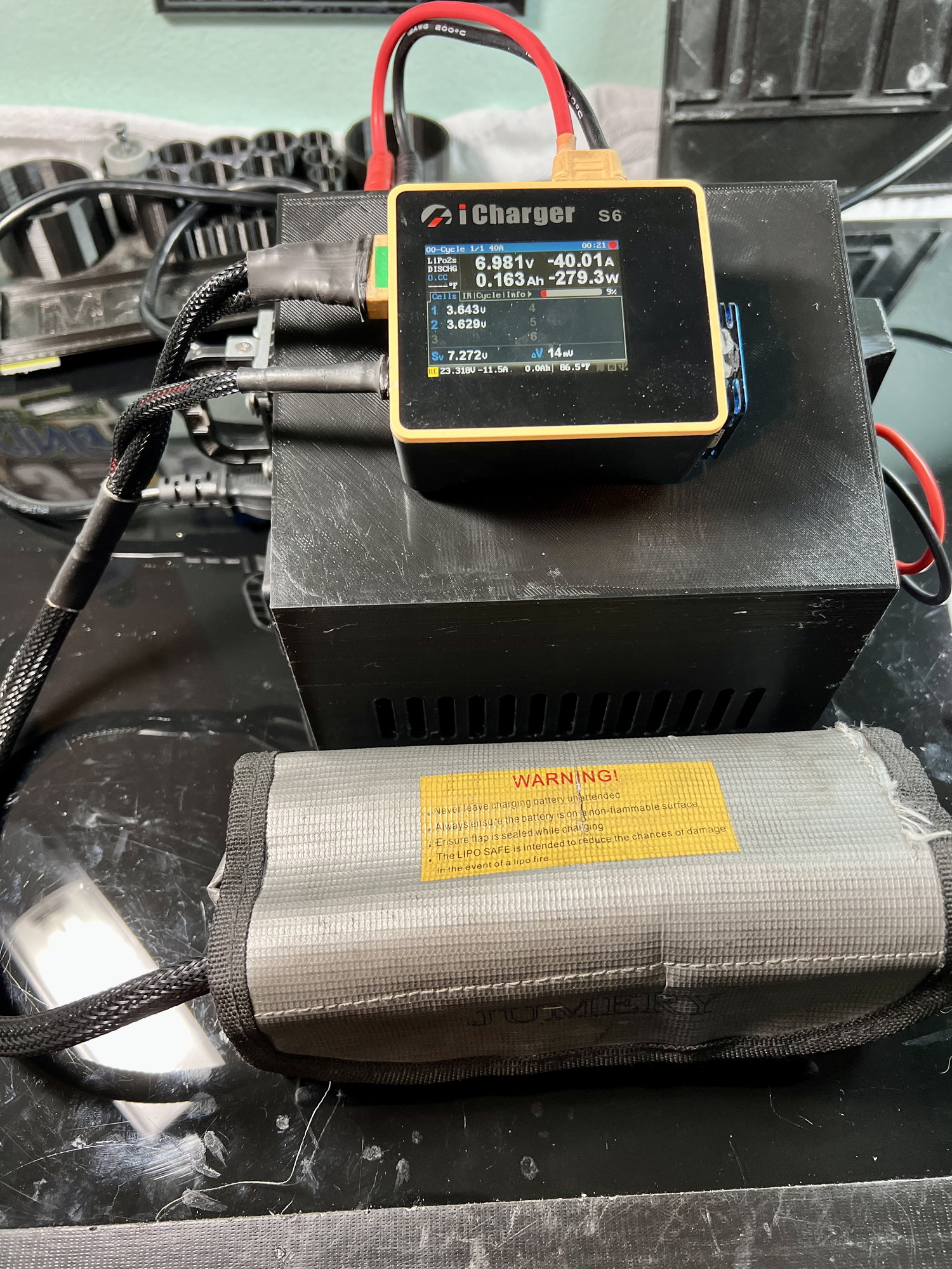
Now, my 2S discharge bank. I have 5 - 1ohm / 100 watt resistors wired in parallel. I followed the instructions for the S6 charger, enabled "extra discharge." I start the discharge, the discharge will run up to 30amps, then drops down to roughly 6amps, then I get an error message that states "output connection break"
Any idea what might be going on?
John
 03-03-2022, 06:09 AM
#512
Have you tried changing the setting to 40 amps. I think your load bank is pushing you to high with the 5th resistor. If you just wanted 30 amps you should remove a resistor.
03-03-2022, 10:00 AM
#513
Tech Addict
iTrader: (24)
Odd.... I changed the discharge amperage to 33amps and it works fine until the very end. I discharge to 3.5v and it'll get to 3.6ish volts and then errors out with an output connection break error and doesn't complete the program. What's up with that?

 06-13-2022, 12:36 PM
#515
Tech Apprentice
Was only able to get it to work with 4 resistors discharging at 25 amps on the x6 thats plenty for me. Designed and printed the legs myself.
06-23-2022, 02:47 PM
#516
Tech Rookie
I'm having trouble getting any "extra discharge" to work on my S6. I've hooked up 5x 1ohm 100w resistors in parallel (0.2 ohm and 500w total) and wired them in between the positive output wire of the iCharger and the positive terminal on the battery, while hooking up the negative and balance leads as normal. Every time I start the discharge, it runs for about one or two seconds then stops and says "done" on the screen.
I've tried at discharge rates anywhere from 10A to 40A, with all 5 resistors or just one... same result. I've updated the software of the S6 to v2.11, I've made sure I have "Extra Discharge Enable" checked in the advanced menu, and I've checked the resistors with a multimeter to make sure they are reading 1ohm each.
Discharging normally at 4-5A without the extra resistors in line works fine.
Any advice would be GREATLY appreciated.
06-25-2022, 07:12 PM
#517
Tech Rookie
I figured it out! Incase anyone else has the same issue:
my problem was that the positive balance lead was spliced into the positive charging lead, and then both were plugged into the resisters. The balance lead needed to be spliced in between the battery and the resisters, not between the resisters and the charger.
my problem was that the positive balance lead was spliced into the positive charging lead, and then both were plugged into the resisters. The balance lead needed to be spliced in between the battery and the resisters, not between the resisters and the charger.
12-24-2023, 12:39 PM
#518
Tech Initiate
Hi,
I'm trying to get the discharge function working on an S6 which should be able to discharge at 40A with a resistor bank
When I start the discharge the current quickly drops so that the discharge power is maintained at 40W. (roughly 6.5 A.)
The firmware I am using is version 2.1.1.
Under the system menu There is a another menu titled 'Input & Power limit. and I think this is the problem.
The power supply option I have selected is
"Discharge Power limit' can only be adjusted in 5w intervals to a maximum value of 40W.
Is there something I need to select to get the charger to ignore this?
Firmware update needed?
I'm trying to get the discharge function working on an S6 which should be able to discharge at 40A with a resistor bank
When I start the discharge the current quickly drops so that the discharge power is maintained at 40W. (roughly 6.5 A.)
The firmware I am using is version 2.1.1.
- The box for extra discharge is ticked and discharge current is set to 40A.
- Regenerative discharge is turned off.
Under the system menu There is a another menu titled 'Input & Power limit. and I think this is the problem.
The power supply option I have selected is
- 9.0v/45.0A/1100W- Not regenerative.
"Discharge Power limit' can only be adjusted in 5w intervals to a maximum value of 40W.
Is there something I need to select to get the charger to ignore this?
Firmware update needed?
04-17-2024, 06:46 PM
#520
Thanks for the update and info.
04-17-2024, 08:12 PM
#521
Can anyone show me a simple way of making this? I got an x6 and spent an hour discharging a 1s 8800 battery.
i can solder wires and things pretty good but in terms of knowing how electrical things work, it took me awhile to figure out the positive and negative side of an a/c power cord. :P
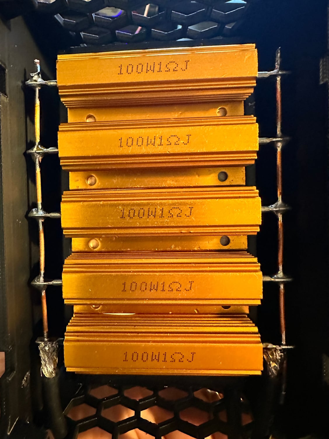
i heard you can get 5x 1 ohm 100 watt resistors and wire them up parallel but what does that mean? A guy at the track even told me that but I still have no idea. Anyone have a guide on how to make this? He said make sure to get a fan cuz it gets hot! I accidentally grazed it and DAMN IT WAS HOT!!! I�d greatly appreciate any info
i can solder wires and things pretty good but in terms of knowing how electrical things work, it took me awhile to figure out the positive and negative side of an a/c power cord. :P
i heard you can get 5x 1 ohm 100 watt resistors and wire them up parallel but what does that mean? A guy at the track even told me that but I still have no idea. Anyone have a guide on how to make this? He said make sure to get a fan cuz it gets hot! I accidentally grazed it and DAMN IT WAS HOT!!! I�d greatly appreciate any info
04-17-2024, 09:50 PM
#522
Can anyone show me a simple way of making this? I got an x6 and spent an hour discharging a 1s 8800 battery.
i can solder wires and things pretty good but in terms of knowing how electrical things work, it took me awhile to figure out the positive and negative side of an a/c power cord. :P
i heard you can get 5x 1 ohm 100 watt resistors and wire them up parallel but what does that mean? A guy at the track even told me that but I still have no idea. Anyone have a guide on how to make this? He said make sure to get a fan cuz it gets hot! I accidentally grazed it and DAMN IT WAS HOT!!! I�d greatly appreciate any info
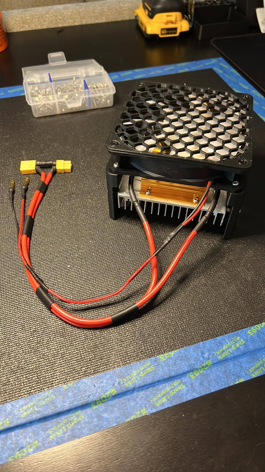
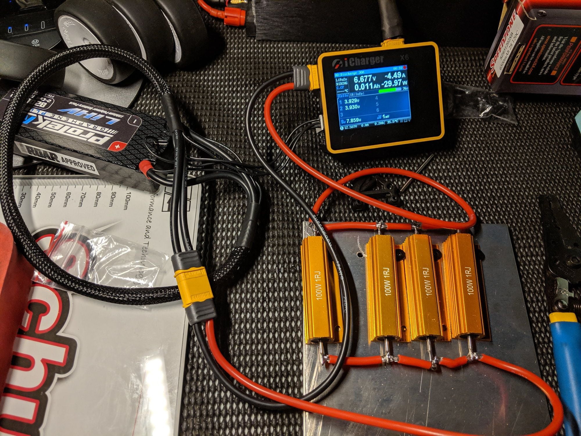
But in this case you are actually looking for a parallel bank, but wired in series with the positive side of the battery. And 5x 1 ohm resistors will only get you about 20A with a 1s.
Here is a pic of a bank in parallel.
 04-17-2024, 10:55 PM
#523
Okay I think I understand it and it�s simple, for the most part. Negative goes to negative but positive goes from charger, resistors in parallel, then battery.
this picture is easy to follow but is there a way to wire up the fans so it can be all self powered like below?
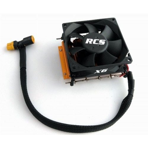
this picture is easy to follow but is there a way to wire up the fans so it can be all self powered like below?
04-18-2024, 05:12 AM
#524
04-18-2024, 06:47 AM
#525
Parallel will look like train tracks. Line the resistors up longitudinally adjacent and run a wire down both ends. Series would be your old school string of Christmas lights.
But in this case you are actually looking for a parallel bank, but wired in series with the positive side of the battery. And 5x 1 ohm resistors will only get you about 20A with a 1s.
Here is a pic of a bank in parallel.
But in this case you are actually looking for a parallel bank, but wired in series with the positive side of the battery. And 5x 1 ohm resistors will only get you about 20A with a 1s.
Here is a pic of a bank in parallel.