


 157Likes
RCHourglass DIY Lap Timing (AKA Cano revised)
 09-19-2023, 02:55 PM
#976
Tech Rookie
Thank you Marco!
I think MLA is powered the same way as the original amp. The MLA30+ comes with another device called Biasing Tee, it has coax input and output with a micro usb port to provide power to the amp via coax cable. So I thought the principle is the same as in the original design and it won't require any modifications.
Upon careful inspection of the MLA30's pcb I noticed one incorrectly soldered component so I am going to stick with payalneg's amp design because I suspect that there might some something wrong with my MLA.
At TP6 I get 3.71V but TP7 makes me wonder because this value is different from the one in the schematic. I will try connecting the R1 to ground and then we'll see what happens.
 09-21-2023, 03:44 AM
#977
09-21-2023, 08:52 AM
#978
Tech Initiate
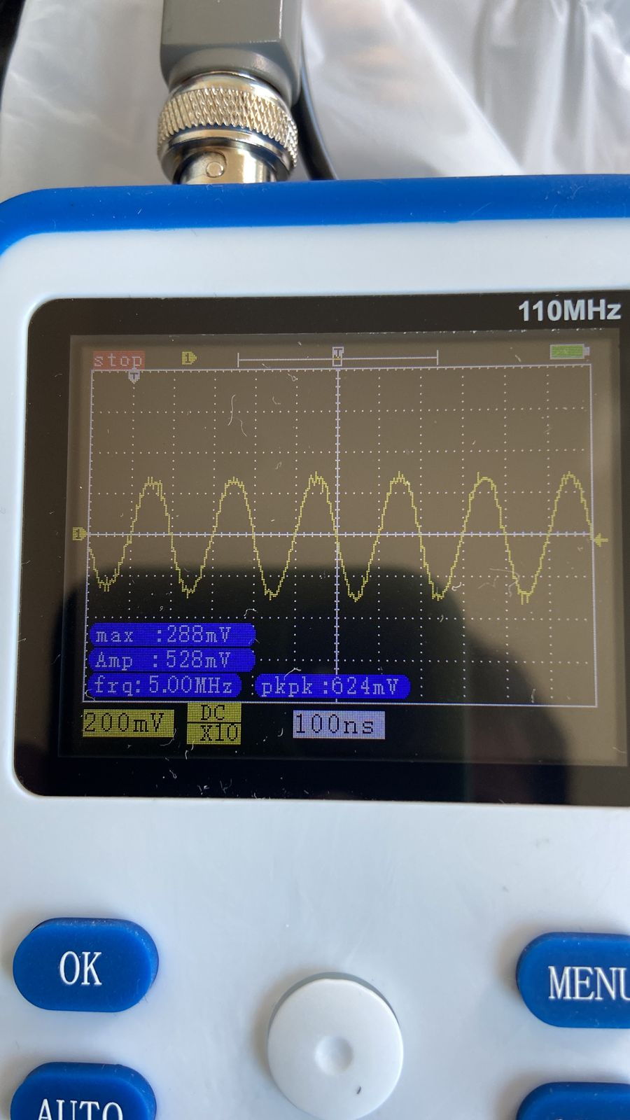
Below is my reading with an oscilloscope (in the loop amplifier, with just one wire at the decoder output), hybrid rc4 transponder.
PSOC connected, measurement made directly at the bnc input.
Now I will continue with my project, I'm sure the decoder is working.
The decoder identifies the transponder and records the reading on the zround normally
The pipe amplifier from what I understand can only cover a loop of 3.5m * 40cm if I'm not mistaken (correct me if I'm wrong)
My track is 4 meters wide so I would need a loop of at least 8 m * 40cm, is there any way to use a loop of this size in the cano amplifier?
In any case, I built both the cano amplifier and the Payalneg's, in the original Payalneg's post there are reports of it working with a loop of up to 10 meters.
09-21-2023, 02:18 PM
#979
The decoder identifies the transponder and records the reading on the zround normally
The pipe amplifier from what I understand can only cover a loop of 3.5m * 40cm if I'm not mistaken (correct me if I'm wrong)
My track is 4 meters wide so I would need a loop of at least 8 m * 40cm, is there any way to use a loop of this size in the cano amplifier?
The pipe amplifier from what I understand can only cover a loop of 3.5m * 40cm if I'm not mistaken (correct me if I'm wrong)
My track is 4 meters wide so I would need a loop of at least 8 m * 40cm, is there any way to use a loop of this size in the cano amplifier?
Original Cano decoder specs are as follows, and the loop size is the width of it, not the length of wire, so 4 meters sholud be in the upper range. I've never used a jumper in my decoder
9'x1' to 12'x1' : No jumpers on loop amplifier.
6'x1' to 8'x1' : Use jumper at J3 on loop amplifier.
3'x1' to 4'x1' : Use jumper at J5 on loop amplifier.
Use 75 ohm coaxial cable with F connectors between the loop amplifier and the phase detector input amplifier.
09-22-2023, 10:53 AM
#980
Tech Initiate
I said that I tested with the amplifier but I wrote it wrong, in fact I only tested it with a wire at the decoder output to make sure that the decoder works.
My problem was actually just the MLA30+ that I couldn't get working.
Today I'm going to start building the cano amplifier and I believe I won't have any more problems.
My problem was actually just the MLA30+ that I couldn't get working.
Today I'm going to start building the cano amplifier and I believe I won't have any more problems.
09-27-2023, 09:33 AM
#981
Tech Initiate
Guys, it's me again.
I finished assembling the project amplifier.
However I am facing some problems, when I measure the reference values by injecting energy through a source everything is ok with the loop amplifier the reference values are correct.
The same happens with the decoder with the psoc turned on and it connected to the notebook, all the reference values match the electrical diagram, I can even read transponders with just 1 wire at the decoder output, the only difference I see from the electrical diagram and in tp7 that instead of having 3.96v as in the diagram I have 4.76v, I believe it is because c1,r1 and the positive of j1 are all soldered together so I am reading the value of r1 in fact, I believe, correct me if I am wrong.
So far so good, right?
The problem is that when I connect the decoder to the loop amplifier the tp7 value drops to 1.36v, so only 1.36v enters the loop amplifier and I end up not being able to read anything through it.
Has anyone ever had this problem with the voltage dropping when connecting the decoder to the loop amplifier?
09-27-2023, 09:51 AM
#982
The voltage dropping so low means a high current draw. Beware of any short you might have in the cable/shield to the F connectors. I had an erratic cable once.
Beware with high current or shorts on 5 volt. Usb port should be current protected, but double check before connecting to a computer. I did even use a simple USB transformer for my first tests.
09-28-2023, 05:44 AM
#983
Tech Initiate
I tested with another cable and had the same result, I don't know what to do.
Nothing makes sense, when measured separately the decoder and the amplifier have the values as they should be, when connected together the amplifier values are all messed up, I will continue to investigate and report here
Nothing makes sense, when measured separately the decoder and the amplifier have the values as they should be, when connected together the amplifier values are all messed up, I will continue to investigate and report here
10-16-2023, 05:35 AM
#984
Tech Apprentice
Hello.
I prototyped a transponder using a readily available 20MHz crystal. It still needs some adjustment, but it seems to be working for now.
The next challenge is to prototype a transponder with an original number using RCHourglass Manager's Firmware Tweak, but RCHourglass Manager does not support the "EXT1X" option.
What should I do?
10-16-2023, 09:54 AM
#985
You sould recompile the asm file with the correct flags and build the HEX file. Make sure the transponder packet is in the DATAMAP segment at CODE 0x0700 (don't touch anything) ad program with your modified HEX file
10-16-2023, 07:15 PM
#986
Tech Apprentice
Thank you mv4wd. I solved the problem myself.
All I had to do was load the firmware (hex file) that had been compiled with the "EXT1X" option using RCHourglass Manager's PIC Programming, enter the desired number using Firmware Tweak, and Program PIC.
All I had to do was load the firmware (hex file) that had been compiled with the "EXT1X" option using RCHourglass Manager's PIC Programming, enter the desired number using Firmware Tweak, and Program PIC.
10-21-2023, 04:00 PM
#987
Tech Apprentice
Hello.
I'm currently making a decoder (loop amplifier). Is it okay to replace parts that are difficult to find?
For example, in a decoder,
R11 4k87 > 4k7
R7 1k21 > 1k2
In a loop amplifier,
R7 1k21 > 1k2
R8 2k87 > 3k
R9 4k53 > 4k7
R10 301 > 300
Is it okay to change it like this?
I'm currently making a decoder (loop amplifier). Is it okay to replace parts that are difficult to find?
For example, in a decoder,
R11 4k87 > 4k7
R7 1k21 > 1k2
In a loop amplifier,
R7 1k21 > 1k2
R8 2k87 > 3k
R9 4k53 > 4k7
R10 301 > 300
Is it okay to change it like this?
10-23-2023, 12:39 AM
#988
The values used are the stadard E96 for 1% tolerance. I think Howard designed that way to have precise bias of the loop amp. You can measure and make sure you have similar values in the pairs that form the differential amplifier, but I've always built with the designed values.
10-23-2023, 02:16 AM
#989
Tech Apprentice
The values used are the stadard E96 for 1% tolerance. I think Howard designed that way to have precise bias of the loop amp. You can measure and make sure you have similar values in the pairs that form the differential amplifier, but I've always built with the designed values.
10-24-2023, 12:02 PM
#990
Tech Initiate
Hello !!
So i made some tests about webserver ... i have trouble after few laps, i have to refresh many times before having all laps ... i maybe missed a delay somewhere .... or bad wifi board, or too much data ... i have to check it ....
I made some test with detection too, difference with original transponder / cano transponder
My configuration:
1/8 Off Road track, 4x0.4m loop, cano amplifer (work better than MLA30 for me)
In this car, original transponder
Reception with original transponder
Result .... i had to refresh many times ....
I add my differents design ( kicad / PCBnew )
Hi Ludo,
Please, do you can help me?
I�m try some kinds of loop amplifiers, and now I�m buyed the MLA30 loop amplifier, but I�m with dificult to integrate on decoder...
Do you can share how do you assambled your system?
Best Regards!
Ederson
Sorry for long time, "baby on board" now ....
about my MLA30+, i put it directly on the decoder, i send pics
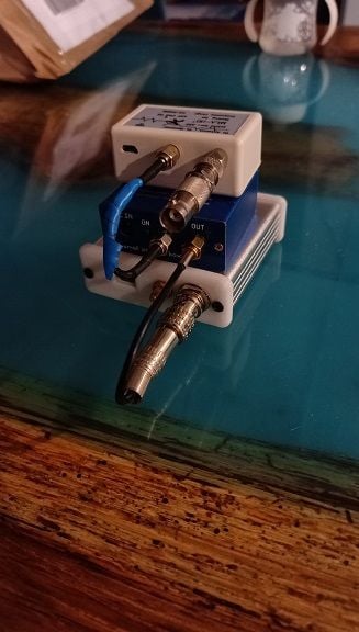
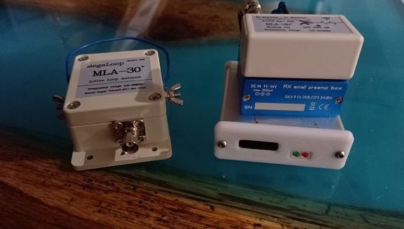
it works good, so , i have 75m coax between decoder/amps and mla loop , i have to try with amplifer near from the loop .
sorry for my bad english ... i'm french
** amp will not work with the original loop amplifer , MLA30 only tested