


 157Likes
RCHourglass DIY Lap Timing (AKA Cano revised)
 02-08-2018, 09:06 AM
#76
Tech Apprentice
On the transponder schematics, the RJ45 connector must not be mounted, only the pin are used to program the PIC.
 02-08-2018, 11:06 AM
#77
Tech Apprentice
Here is some log from an AMB TransX 160 Numer 0951678
RC Hourglass v0.1 beta
MONITOR MODE ON
FC0A62000000000000000000 0003B7CE
FC0A00080006000000000000 0006F1D5
F91600000141261818000301 0007762A
FC0A7AA97A52CED603200401 00090655
FC0A80000030020000000000 000953B8
FC0A42000000000000020000 000965B5
FC0A02089004800000528808 000A0ECC
FC0AA4090046244420888080 000A566F
FC0A21144A92614251A88400 000A6051
FC0A20008000800000018000 000A687E
FC0A240000000002DAF27680 000A74AF
FC0A001F9AFFFFFFE0233FF8 000A7CDB
FC0A31F830E10104160010A0 000B207A
Preamble seen to be FC0A
02-08-2018, 02:25 PM
#78
Hi mroc, the reads that you get seem very different from what I read with a RC4 transponder. All those 0 in the packets are quite strange, also the reading should be 1 or 2 msec apart (last column is the timestamp in hex). The reading should be very fast. I'm afraid you're loosing a lot of packets due to bad decoding (that is preamble detector not triggering). The blu led on the PSOC board is directly connected to the preamble detector, so it should be bright on when the transponder is read. Do you have the same situation with a RC transponder?
02-08-2018, 10:07 PM
#79
Tech Apprentice
Hi mroc, the reads that you get seem very different from what I read with a RC4 transponder. All those 0 in the packets are quite strange, also the reading should be 1 or 2 msec apart (last column is the timestamp in hex). The reading should be very fast. I'm afraid you're loosing a lot of packets due to bad decoding (that is preamble detector not triggering). The blu led on the PSOC board is directly connected to the preamble detector, so it should be bright on when the transponder is read. Do you have the same situation with a RC transponder?
It was only to test.
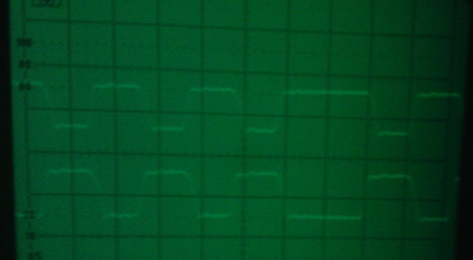
I made some pre-test with the ESP32, using the RMT ( for infrared remote control ) to build the signal from transponder, here is a pics from signal on the pin, see not so bad, using the processor only to load the data waveform.
02-09-2018, 01:28 AM
#80
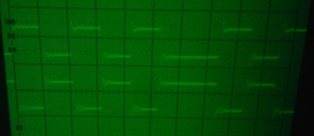
That looks great! I might be wrong, but from the image it seems like you're swapping every 3 waveform periods, not four. Next thing you want to investigate is how the pair align (signal and signal negate). I guess it's not going to a problem, but I attached the scope to my first design and found out the two slew rates and timing were different. I then had to change design to use the CWG module. Last drive the antenna and check the waveform, and hope the wifi is not too noisy 
This is my first output:
This is current design... much better:
This is my first output:
This is current design... much better:
02-09-2018, 10:00 AM
#81
Tech Apprentice
For the AMB, the battery was dead,,,, and now, I see a frequency of 3.68 Mhz... shit
02-09-2018, 02:50 PM
#82
Tech Rookie
Hi guys, I was buy the main components on AliExpress. Now i will need wait for until 60 day to receive here the components.... :|
I don't understand the last message from Thor, do you find a diferent frequency with AMB transponders?
Regards,
Ederson
I don't understand the last message from Thor, do you find a diferent frequency with AMB transponders?
Regards,
Ederson
02-10-2018, 08:52 PM
#83
Tech Initiate
I have a transponder made using a PIC16F18323 now. I have made the the changes needed to make the PIC asm code work on that chip. I also moved the ant loop to the RC1 and RC2 pins to allow debugger to stay connected. I now have known working hardware now.
I know enough about PIC asm to make changes to it and understand what its doing. I don't think I can write a good ADC sample code with a running average in PIC asm.
I had been working on the C code before I got the chips in and I couldn't get it working on the PIC16F18313. It was pain though as I had to pull the chip out of that transponder to reprogram them.
I just took a fresh look at the C code and seen where I made some mistakes with my PPS setup both pins where being set to the CWG1OUTA output. I will work on this some more this week. Will update when I get somewhere.
02-11-2018, 02:01 AM
#84
Tech Apprentice
I have a transponder made using a PIC16F18323 now. I have made the the changes needed to make the PIC asm code work on that chip. I also moved the ant loop to the RC1 and RC2 pins to allow debugger to stay connected. I now have known working hardware now.
I know enough about PIC asm to make changes to it and understand what its doing. I don't think I can write a good ADC sample code with a running average in PIC asm.
I had been working on the C code before I got the chips in and I couldn't get it working on the PIC16F18313. It was pain though as I had to pull the chip out of that transponder to reprogram them.
I just took a fresh look at the C code and seen where I made some mistakes with my PPS setup both pins where being set to the CWG1OUTA output. I will work on this some more this week. Will update when I get somewhere.
I know enough about PIC asm to make changes to it and understand what its doing. I don't think I can write a good ADC sample code with a running average in PIC asm.
I had been working on the C code before I got the chips in and I couldn't get it working on the PIC16F18313. It was pain though as I had to pull the chip out of that transponder to reprogram them.
I just took a fresh look at the C code and seen where I made some mistakes with my PPS setup both pins where being set to the CWG1OUTA output. I will work on this some more this week. Will update when I get somewhere.
I don't if, on the decoder part, will be possible to change the frequency to be higher, and then we put on the analog circuit a mixer like the NE612 or a passive like ASK-1 transformer, also we must provide an DDS frequency FO.
If we have 20Mhz clock for BPSK decoding, then with 15Mhz ( 20 - 5 ), we have transponder on 5Mhz decoding. With 16Mhz32, we decode the 3.68 Mhz transponder, so, without to change the hardware, we can decode a lot of transmission.
Thor
02-11-2018, 02:56 AM
#85
Tech Apprentice
Here are some waweform from the Amb TransX 160 #0951678
The zip file is a dump from the scope memory in cdv format
Thor
The zip file is a dump from the scope memory in cdv format
Thor
02-12-2018, 04:38 AM
#86
Tech Apprentice
Here some idea.. using a AD9833 as frequency synth and an analog RF mixer to
change the input frequency from the transponder.
The MPU have to provide a 25 Mhz clock to the DDS, and will program the frequency
output from the DDS.
Then applied to the mixer, it will split up or down the frequency to enter the decoder.
Thor
change the input frequency from the transponder.
The MPU have to provide a 25 Mhz clock to the DDS, and will program the frequency
output from the DDS.
Then applied to the mixer, it will split up or down the frequency to enter the decoder.
Thor
02-13-2018, 05:36 PM
#87
Tech Initiate
Hello,
how can I generate custom transponder ID CODE:
; 2351957
Message1 DT 0XF9, 0X16, 0XE1, 0XCB, 0X12, 0X1C, 0XC9, 0XD6, 0XC3, 0XE0, 0XFF, 0X0F
Status1 DT 0XF9, 0X16, 0XDA, 0XE7, 0X94, 0X77, 0XE9, 0X3C, 0X91, 0XD7, 0XC3, 0XCC
Status2 DT 0XF9, 0X16, 0XEC, 0X50, 0X55, 0X92, 0XE2, 0X23, 0X61, 0XD4, 0XF0, 0X0C
Status3 DT 0XF9, 0X16, 0X36, 0X58, 0X15, 0X1B, 0XC8, 0XC3, 0X62, 0X14, 0X3C, 0X00
Status4 DT 0XF9, 0X16, 0X0E, 0X29, 0XBA, 0XE0, 0X3E, 0XE3, 0X62, 0XDB, 0XC0, 0XC3
Status5 DT 0XF9, 0X16, 0X36, 0X55, 0X57, 0X09, 0XFB, 0X3F, 0X91, 0X27, 0X00, 0XF0
Status6 DT 0XF9, 0X16, 0X0E, 0XFE, 0XF0, 0X8A, 0X22, 0X3C, 0X52, 0X1B, 0X3F, 0XF3
Status7 DT 0XF9, 0X16, 0XD7, 0XA8, 0X10, 0X77, 0XD1, 0X23, 0XA2, 0XD7, 0XC3, 0X3C
and is it RC4 compatible or not?
thank you for answer.
02-14-2018, 08:47 AM
#88
Tech Apprentice
Their is a program from cano what generate some number, but without status and also, don't generate the same sequence.
02-14-2018, 10:15 AM
#89
The published transponder firmware works with Mylaps RC4 decoder unless it's patched to the last firmware that cuts out all older transponders (MRT/AMB). There's a specific thread about this.
The numbers given are taken from Cano transpoder firmware.
The openAST project has a program to encode the numbers. Unfortunatley I don't think it's 100% correct. But the main problem is for the status messages. As far as I know the content and the relation of the 7 status messages with the transponder packet is unknown. Also it seems like RC4 decoder will reject transponders that do not send status packets. This is not 100% true, since older AMB transponder do not send status packets, but are correctly detected. This means that somehow in the ID itself there is some check digit or version number that says if the status packet is to be expected or not. So you might be able to encode your custom number but Mylaps decoder might discard it. RCHourglass should read it.
If anybody has better information please submit.
02-15-2018, 08:23 AM
#90
Tech Rookie
Hi, i�m interesting in the circuit, and i buy the componenents to complete and testing in my club, but i have some questions to Mv4wd:
in the 16F18313 PIC (Transponder) it is neccesary a 0.1uF Cap in Vdd-Vss?
For the transponder�s antenna loop, it is possible to mount with 0.1mm wire?
I try with perfboard for final use in my club track, there are any tips or advice for connect the different components?
Thanks in Advice! Great Job Guys.