


 157Likes
RCHourglass DIY Lap Timing (AKA Cano revised)
 05-23-2023, 05:38 PM
#856
Tech Rookie
Hi Ludo,
Please, do you can help me?
I´m try some kinds of loop amplifiers, and now I´m buyed the MLA30 loop amplifier, but I´m with dificult to integrate on decoder...
Do you can share how do you assambled your system?
Best Regards!
Ederson
Please, do you can help me?
I´m try some kinds of loop amplifiers, and now I´m buyed the MLA30 loop amplifier, but I´m with dificult to integrate on decoder...
Do you can share how do you assambled your system?
Best Regards!
Ederson
 05-23-2023, 05:41 PM
#857
Tech Rookie
[QUOTE=zouky23;15782814]Hello !!
So i made some tests about webserver ... i have trouble after few laps, i have to refresh many times before having all laps ... i maybe missed a delay somewhere .... or bad wifi board, or too much data ... i have to check it ....
I made some test with detection too, difference with original transponder / cano transponder
My configuration:
1/8 Off Road track, 4x0.4m loop, cano amplifer (work better than MLA30 for me)
In this car, original transponder
Reception with original transponder
Result .... i had to refresh many times ....
I add my differents design ( kicad / PCBnew )
Hi Ludo,
Please, do you can help me?
I´m try some kinds of loop amplifiers, and now I´m buyed the MLA30 loop amplifier, but I´m with dificult to integrate on decoder...
Do you can share how do you assambled your system?
Best Regards!
Ederson
07-04-2023, 02:41 PM
#858
Tech Rookie
Greetings to all.
I've been trying to advance for 2 days but I'm a noob way over my head.
We have a RC3 decoder at my local club and the only transponders we are able to use, are the Mylaps "Hybrid" (with two wires). They are as expensive as the cars we use.
I'd like to DIY a transponder, but I can't find the files to send to PCBWay (or any other PCB maker) or the list of components.
I've read until my eyes blurred and it seems some people made PCB designs but I can't find them anywhere. Are they for sale maybe? I'm from Spain, so it would be hard (expensive) to buy from the USA.
Any help is appreciated.
Have a good day!
07-06-2023, 09:14 AM
#859
Tech Rookie
Greetings to all.
I've been trying to advance for 2 days but I'm a noob way over my head.
We have a RC3 decoder at my local club and the only transponders we are able to use, are the Mylaps "Hybrid" (with two wires). They are as expensive as the cars we use.
I'd like to DIY a transponder, but I can't find the files to send to PCBWay (or any other PCB maker) or the list of components.
I've read until my eyes blurred and it seems some people made PCB designs but I can't find them anywhere. Are they for sale maybe? I'm from Spain, so it would be hard (expensive) to buy from the USA.
Any help is appreciated.
Have a good day!
I've been trying to advance for 2 days but I'm a noob way over my head.
We have a RC3 decoder at my local club and the only transponders we are able to use, are the Mylaps "Hybrid" (with two wires). They are as expensive as the cars we use.
I'd like to DIY a transponder, but I can't find the files to send to PCBWay (or any other PCB maker) or the list of components.
I've read until my eyes blurred and it seems some people made PCB designs but I can't find them anywhere. Are they for sale maybe? I'm from Spain, so it would be hard (expensive) to buy from the USA.
Any help is appreciated.
Have a good day!
Answering myself, in case someone needs it.
I found this:
Since I can't post links... The webpage is oshpark.com followed by shared_projects followed by xsPLwajU
It has the PCB design and the component list.
07-29-2023, 05:47 AM
#860
Tech Initiate
Good morning everybody.
I bought the components to carry out the project, the loop amplifier I will use the lma-30+.
Has anyone had success with this configuration?
Is there any pcb gerber file for the decoder?
Sorry for the amount of questions I read almost the entire topic but as it's been a long time maybe someone can give me valuable information.
I thank everyone
07-31-2023, 08:14 AM
#861
There's no 'official PCB' for the project, some have been kindly published by other users. I think no one has published a detailed LMA 30 schematic, and I've never used one.
07-31-2023, 09:21 AM
#862
Tech Initiate
yes I use this configuration. Reception is great.
Remember to tune the pot inside the loop amplifier. I had to slightly reduce the gain for best performance.
Remember to disable the 5V antenna power supply on decoder too.
07-31-2023, 01:01 PM
#863
Tech Initiate
I don't know if I understand correctly, the lma30+ has a 5 volt power input correct? should i not use it? would it be this ?
07-31-2023, 04:32 PM
#864
Tech Initiate
This little box works as a sort of power injector.
The RCHourglass decoder was originally intented to be used with Howard Cano's loop amplifier instead ot the MLA-30+, so it supplies 5V on the coaxial cable to power the loop amplifier.
As MLA-30+ is self powered (through the little box) you don't have to provide the 5V power supply from the decoder. I don't know if the "little box" is somehow protected, in doubt I don't power it
 .
.
Last edited by mdenadal; 07-31-2023 at 04:51 PM.
07-31-2023, 04:36 PM
#865
Tech Apprentice
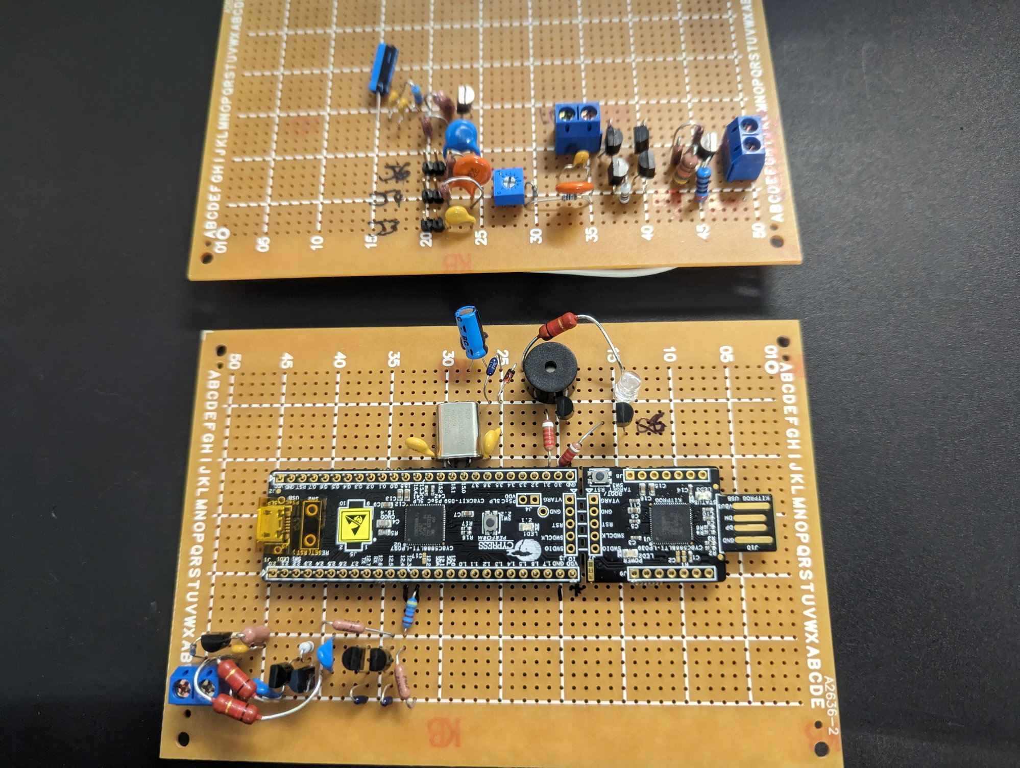
Well I gave it a try, unfortunately I can't seem to get the loop to pick anything up. Decoder seems to work, the RCHourGlass Manager program is able to beep and flash the LED. I think the issue may be with my loop amp.
I'm in way over my head though and don't really know what else to do. Test points all seemed to be OK, but I don't really know what to do from here.
I may just reorder loop amp parts and redo that.
I'm in way over my head though and don't really know what else to do. Test points all seemed to be OK, but I don't really know what to do from here.
I may just reorder loop amp parts and redo that.
08-01-2023, 12:51 AM
#866
Double check transistor connection/orientation (but if you say all test voltages match, they should be fine). Do you have access to an oscilloscope?
08-01-2023, 02:03 AM
#867
Tech Apprentice
I unfortunately do not. I went and bought all components again today to have another try. I struggled with the loop amp build as I started to follow the wiki layout but then got a little lost, more than likely something I have done. Will plan out better next build.
08-01-2023, 08:42 AM
#868
Tech Initiate
MLA-30+ comes in two parts: the loop amplifier itself and a box with 2 sma connectors and a usb style port.
This little box works as a sort of power injector.
The RCHourglass decoder was originally intented to be used with Howard Cano's loop amplifier instead ot the MLA-30+, so it supplies 5V on the coaxial cable to power the loop amplifier.
As MLA-30+ is self powered (through the little box) you don't have to provide the 5V power supply from the decoder. I don't know if the "little box" is somehow protected, in doubt I don't power it.
This little box works as a sort of power injector.
The RCHourglass decoder was originally intented to be used with Howard Cano's loop amplifier instead ot the MLA-30+, so it supplies 5V on the coaxial cable to power the loop amplifier.
As MLA-30+ is self powered (through the little box) you don't have to provide the 5V power supply from the decoder. I don't know if the "little box" is somehow protected, in doubt I don't power it
.This week all the components should arrive so I'm going to venture out!
I hope it works out
08-01-2023, 11:05 AM
#869
Tech Adept
MLA-30+ comes in two parts: the loop amplifier itself and a box with 2 sma connectors and a usb style port.
This little box works as a sort of power injector.
The RCHourglass decoder was originally intented to be used with Howard Cano's loop amplifier instead ot the MLA-30+, so it supplies 5V on the coaxial cable to power the loop amplifier.
As MLA-30+ is self powered (through the little box) you don't have to provide the 5V power supply from the decoder. I don't know if the "little box" is somehow protected, in doubt I don't power it.
This little box works as a sort of power injector.
The RCHourglass decoder was originally intented to be used with Howard Cano's loop amplifier instead ot the MLA-30+, so it supplies 5V on the coaxial cable to power the loop amplifier.
As MLA-30+ is self powered (through the little box) you don't have to provide the 5V power supply from the decoder. I don't know if the "little box" is somehow protected, in doubt I don't power it
.I have two setups, one where the MLA30 is supplied by the original little power box and the other one where the MLA30 is just hooked to the decoder. Both work and there are no significant differences. Both have about 60-70cm of range above the 4m wide loop.
When using the original MLA30 power supply, I admit it would be cleaner if the supply from the decoder is cut. Maybe reception is even better then?
Andreas
08-01-2023, 11:37 AM
#870
Tech Rookie
I ordered some of the v1 and v2 boards and the components to try and make some but i've not had any luck.
I've been able to program the PIC whilst not mounted to the board but as soon as it is mounted it looks like i'm getting a short. If I connect the SOIC8 programmer whilst on the board it says too high current draw.
From what I can tell everything appears to be mounted cleanly. I'm using a hot plate to flow the paste with the components and everything seems to match up with the schematics.
I have no real experience in fault finding electronics like this.
Is anyone still actively working on these that might be able to point out either what points to test on the board or a likely fault i've made?
I'll see if I can get some images up of the board.
Thanks in advance.