


 157Likes
RCHourglass DIY Lap Timing (AKA Cano revised)
 10-09-2018, 11:28 AM
#331
Tech Initiate
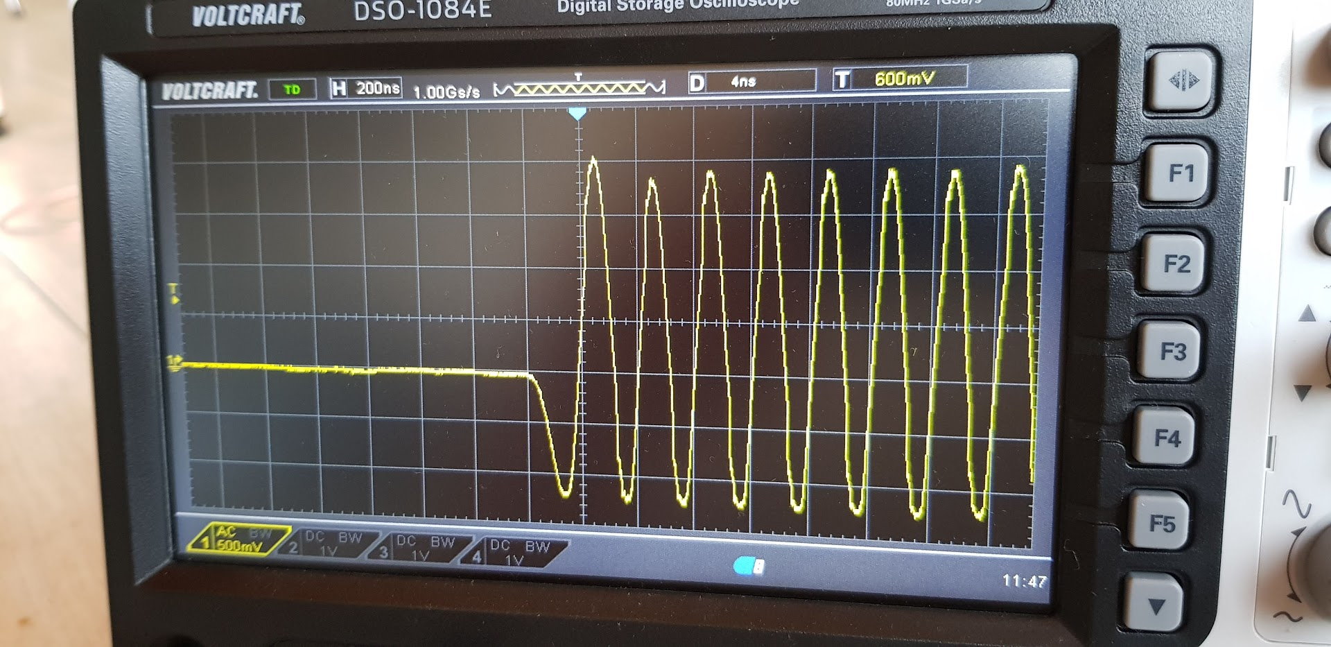
Have tested again today. With 3m loop I get similar signals. I have a trim capacitor installed, but the signal changes very little. Even without a capacitor at all, I get similar signals. The flipping unfortunately brings nothing.
Here is a screenshot during the time measurement with notebook, r11 so not expanded.
On the track, I can count almost all rounds when I build the loop in the braking zone in front of a hairpin. once you are a little on the throttle (1/10 brushless) , nothing is counted.
Have am AMB system at home for the next time. I'm going to measure a few signals with it ......
 10-10-2018, 02:41 AM
#332
Can you please check the phase revert part of the signal... That's the key point to decoding... steady sinusoidal state should not be very upset by different loop sizes... only amplitude... but on phase reversal there might be some glitches.
10-21-2018, 07:39 AM
#333
Tech Initiate
Sorry, I had no time the last days. What do you mean exactly. related to the amb decoder?
10-22-2018, 04:10 AM
#334
The most important part of the signal for decoding is when the sine wave revers phase, as you can see in my screenshot. That part might change the waveform with loop tuning, whereas the 'stable' part will still look sine wave (maybe a little lower). But the phase reversal requires more bandwidth to be correclty followed by the circuit. That's why I asked to check that part of the wave when you change lookp
10-30-2018, 03:51 AM
#335
Tech Rookie
Hello all!
I wonder if anyone have a complete list of materials to buy for the transponder the decoder and the amplifier?
Regards
I wonder if anyone have a complete list of materials to buy for the transponder the decoder and the amplifier?
Regards
11-02-2018, 08:39 AM
#336
Tech Apprentice
iTrader: (2)
I build mine on a perfboard and still got a weak detection (it only get if I pass really slow) at 12ft our track has 14ft lines.
I will try the lm319 amplifier .
this is a decoder amplifier pcb from howardcano files I just add the references .
https://oshpark.com/shared_projects/XMEHrA6q
I will try the lm319 amplifier .
this is a decoder amplifier pcb from howardcano files I just add the references .
https://oshpark.com/shared_projects/XMEHrA6q
11-05-2018, 05:16 AM
#337
Sorry to hear about you unsuccess with the build. I had 'weak' signals or missed laps when the system connections were not good (especially f connectors). We've used the decoder on carpet track with 1/10 buggies, in the straight where the cars are fast and on full throttle (wire on the ground above the carpet fixed with some adhesive strip). Also with the wire 2 cm underground with 1/8 buggies on a grass track (here it's a slower location).
In both case I've used 2,5m*30 cm loop, never make a test with a rack above the track.
Probably a reference PCB and BOM could help a lot with this kind of issues. I'll try to develop my own PCB but I'll need to test it well before making it public.
Marco
In both case I've used 2,5m*30 cm loop, never make a test with a rack above the track.
Probably a reference PCB and BOM could help a lot with this kind of issues. I'll try to develop my own PCB but I'll need to test it well before making it public.
Marco
11-09-2018, 02:18 AM
#338
Tech Rookie
Hello guys!
I have not managed to get the transponder working... Can anyone help me with some qustions?
Is there any position in the components?
How can we check if it�s working? The led blinks?
How many volt�s should I input?
Can you help
I have not managed to get the transponder working... Can anyone help me with some qustions?
Is there any position in the components?
How can we check if it�s working? The led blinks?
How many volt�s should I input?
Can you help
11-09-2018, 09:01 AM
#339
Hi All,
I am interested in this project as I have a few gripes with AMD/MYLAPS. if you are not aware in the full scale racing you can no longer buy your own transponder, you have to pay a yearly service fee to Mylaps plus an upfront cost. how long before this trickles down?
The first question I can't seem to find an answer too, is why not more RFID and off the shelf hardware?
11-09-2018, 09:39 AM
#340
11-09-2018, 09:59 AM
#341
11-15-2018, 06:41 AM
#342
Tech Rookie
Hello again!
I finally get my transponder to blink( several assembly errors), my question is:
Why is it not being detected in my AMB RC3 version 3.xx Decoder? Any trick I`m missing? Any check I can make to make sure every place has the right current and continuity?
Can anyone help?
Regards
I finally get my transponder to blink( several assembly errors), my question is:
Why is it not being detected in my AMB RC3 version 3.xx Decoder? Any trick I`m missing? Any check I can make to make sure every place has the right current and continuity?
Can anyone help?
Regards
11-15-2018, 07:57 AM
#343
If the led blinks, unless you've shorted and fried something in the PIC, the transponder is working and output signal should be on pin 6 and 7 of the PIC. Make sure you don't have a short and measure continuity of the wire antenna loop. Check condenser and resistor values. Make sure you have the right crystal frequency (5Mhz).
11-15-2018, 08:56 AM
#344
Tech Apprentice
iTrader: (2)
Hello,
I the schematics public ? Today i check the lm319 amps. without the condensator on the loop, signal from my transponder, with a ferrit antennae with same inductance as the normal is
allmost four time more powerful as the standard AMB TX transponder fully charged.
Thor
I the schematics public ? Today i check the lm319 amps. without the condensator on the loop, signal from my transponder, with a ferrit antennae with same inductance as the normal is
allmost four time more powerful as the standard AMB TX transponder fully charged.
Thor
did you use this lm319 amplifier with rchourglass decoder?
thank you!!
11-16-2018, 12:51 AM
#345
Tech Rookie
Hello again,
Still not detecting my transponder...
2 more things:
The antenna 100 R resistors shown in the schematics is 100k or 100"ohm"? Because there is almost no current on the antenna.
The Crystal is 5MHZ is it enough to be 5MHZ or it must be a specific one? Is there a way to test the Crystal?
Regards:
Still not detecting my transponder...
2 more things:
The antenna 100 R resistors shown in the schematics is 100k or 100"ohm"? Because there is almost no current on the antenna.
The Crystal is 5MHZ is it enough to be 5MHZ or it must be a specific one? Is there a way to test the Crystal?
Regards: