


 157Likes
RCHourglass DIY Lap Timing (AKA Cano revised)
 05-07-2018, 12:13 AM
#211
To make the program start so it responds as a USB serial port you need at least to connect the 5MHz crystal and the two capacitors C4 and C5.
 05-07-2018, 01:17 AM
#212
Tech Rookie
thank you fot the support
05-11-2018, 02:32 AM
#213
Tech Apprentice
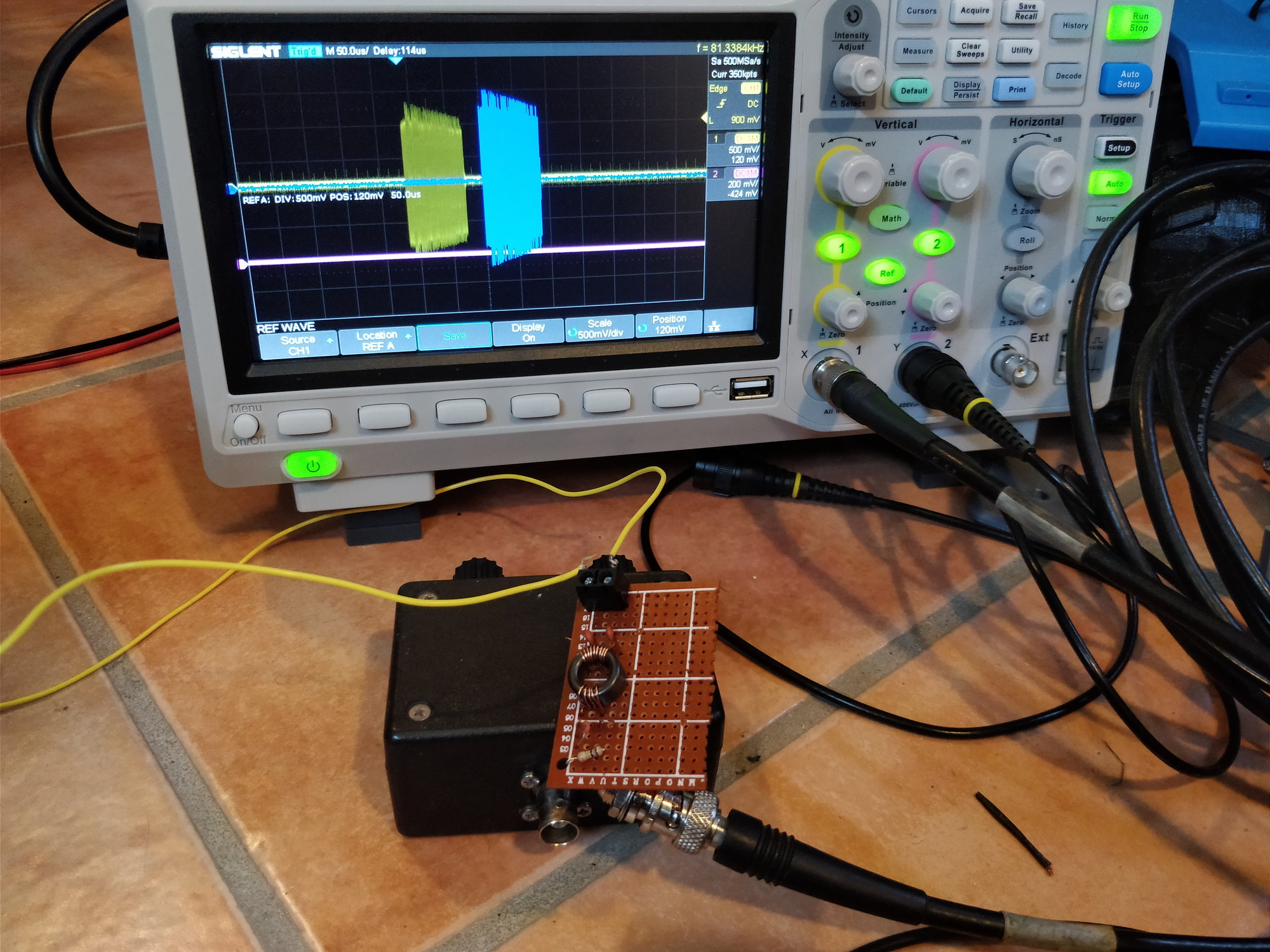
I have managed to make a working copy of the black original amb loop box. The blue is the original box and yellow is the copy. It is a bit less in signal strength but it works. The schematics that I have on my project site from a few years back was wrong and did not work. But now I have made a change so it works. It can have some improvements made probably to get closer to the same signal strength. Will redraw schematics in the week to come and update the schematics in my github project.
Is this something of interest to the RCHourglass project or is the active parts enought?
05-11-2018, 12:45 PM
#214
Tech Apprentice
I have managed to make a working copy of the black original amb loop box. The blue is the original box and yellow is the copy. It is a bit less in signal strength but it works. The schematics that I have on my project site from a few years back was wrong and did not work. But now I have made a change so it works. It can have some improvements made probably to get closer to the same signal strength. Will redraw schematics in the week to come and update the schematics in my github project.
Is this something of interest to the RCHourglass project or is the active parts enought?
on a loop 1m10x0.69 I have a detection to 5m without problem
on the 10mx0.7m loop, the detection is 0.5m I think I have to change the capacitor from 47pf to 12 pf
the 10m loop has an L = 28uH, the 1m10 loop 4.8uH.
All the test i have done are with the wire only on the grass, not a real MX line.
Here are some interesting link:
Loop antena calculator: http://www.dl0hst.de/magnetlooprechner.htm
other but in French: http://alloza.eu/david/WordPress3/?p=24
https://www.vfdb.org/aktuell/wp-content/uploads/2016/07/Article_pa0rdt-Mini-Whip.pdf
thor
05-14-2018, 04:03 AM
#215
05-14-2018, 04:13 AM
#216
Have you been able to capture some packets with the scope?
I think MX and Kart transponders have a higher supply voltage with a ferrite coil to produce stronger fields. Also I'm afraid for such a short range the normal 'antenna' formula might not be of help. The model is more that of a small field inducing current on one of the two wires. The transponder in the middle of the loop causes the lower signal since the two wires voltages cancel each other. Of course capacitors and inductance of the loop control the sensitivity that should be max at carrier frequency.
05-14-2018, 04:28 AM
#217
Tech Apprentice
05-14-2018, 04:40 AM
#218
Tech Apprentice
When I compared the loop box in real world on our track, the home built had double the signal strength in the timing software. And the view in the scope had higher signal also. So it works great as replacement for original AMB RC3 decoder atleast.
05-14-2018, 01:00 PM
#219
Tech Apprentice
Does this work at 3.58 MHz? I think it might be possible to change the timebase of the decoder, but maybe some of the capacitors need to be tuned. Also it's not confirmed that the preamble and packet have the same size/meaning or RC transponders.
Have you been able to capture some packets with the scope?
I think MX and Kart transponders have a higher supply voltage with a ferrite coil to produce stronger fields. Also I'm afraid for such a short range the normal 'antenna' formula might not be of help. The model is more that of a small field inducing current on one of the two wires. The transponder in the middle of the loop causes the lower signal since the two wires voltages cancel each other. Of course capacitors and inductance of the loop control the sensitivity that should be max at carrier frequency.
Hello,
The signal power are the same as i can see ( Amp Tranx 160 / 0951678 ). I will try to use a mixer ad831A to adjust the frequency from 3.58 to 5 Mhz. I think if i use an 1.42 Mhz signal to transpose the frequency.
The only problem will be the preamble ...
The pic transponder work with this https://www.bechronized.com/motocross-mx-supercross-sx-1 system,
But i don't understood how it works, has i have seen, the loop send a busk 125khz signal, and the transponder return a 5 Mhz bask signal, modulated on a 315Mhz carrier (chip are: 5150 cpu and ??? )
Thor
05-17-2018, 11:29 AM
#220
Tech Rookie
Hi Guys - at first many greetings from germany and a great respect to all involved in this great project!
The original loopbox is a balun: this smart board converts the unbalanced to balanced signal on 75ohm Cable - with filtering of noise. With it you can use up to 100m signal cable between loop and decoder without any amplyfier.
I rebuild my own loopbox with same signal quality like original one... tested on RC3 RC4 and alternate decoders...
My question is to use this instead the amplifier on the decoder described here - because most tracks have the mylaps loop and box installed here and need only an alternate decoder system....like this interesting project here...
kind regards
Danny
Last edited by DannyRC2; 05-17-2018 at 10:29 PM.
05-18-2018, 06:23 AM
#221
Tech Apprentice
Hi Guys - at first many greetings from germany and a great respect to all involved in this great project!
The original loopbox is a balun: this smart board converts the unbalanced to balanced signal on 75ohm Cable - with filtering of noise. With it you can use up to 100m signal cable between loop and decoder without any amplyfier.
I rebuild my own loopbox with same signal quality like original one... tested on RC3 RC4 and alternate decoders...
My question is to use this instead the amplifier on the decoder described here - because most tracks have the mylaps loop and box installed here and need only an alternate decoder system....like this interesting project here...
kind regards
Danny
The original loopbox is a balun: this smart board converts the unbalanced to balanced signal on 75ohm Cable - with filtering of noise. With it you can use up to 100m signal cable between loop and decoder without any amplyfier.
I rebuild my own loopbox with same signal quality like original one... tested on RC3 RC4 and alternate decoders...
My question is to use this instead the amplifier on the decoder described here - because most tracks have the mylaps loop and box installed here and need only an alternate decoder system....like this interesting project here...
kind regards
Danny
I the schematics public ? Today i check the lm319 amps. without the condensator on the loop, signal from my transponder, with a ferrit antennae with same inductance as the normal is
allmost four time more powerful as the standard AMB TX transponder fully charged.
Thor
05-18-2018, 08:13 AM
#222
Wellcome aboard. It should be tested if the phantom power does not upset the balun and the impedance and signal level match. I'll try to build the balun and see the results. It would be nice to work with both loops if possible
05-21-2018, 01:45 AM
#223
Tech Apprentice
EDIT: i didnt remember that i already posted this...
Here are the schematics for the working loop box i made: https://github.com/condac/openAST/ra...box_schema.png
Here are the schematics for the working loop box i made: https://github.com/condac/openAST/ra...box_schema.png
05-24-2018, 01:42 AM
#224
Tech Rookie
I mean there is a missing Resistor in your loop condac... If you measure the original box you will get 100kOhm on RG59 output side and also on loop input side...
thats the missing resistor maybe your box gets than stronger signal.
My self designed box works with 15 nF and 2x 1nF and the original core 6:14 measured with mylaps up to 200 hits in 1m testing loop not under ground, in real race approx 120 - 160 hits
The original core couldnt detect yet but has measured Douside 10.27mm Dinner 5.75mm x High 3.85mm (Da 0.404inch Di 0.226inch H 0.151inch) and no color.
I have tried a T44-2 core but hits 60-100....not acceptable. i must investigate what core its exactly is - any hints????
thats the missing resistor
maybe your box gets than stronger signal.My self designed box works with 15 nF and 2x 1nF and the original core 6:14 measured with mylaps up to 200 hits in 1m testing loop not under ground, in real race approx 120 - 160 hits
The original core couldnt detect yet but has measured Douside 10.27mm Dinner 5.75mm x High 3.85mm (Da 0.404inch Di 0.226inch H 0.151inch) and no color.
I have tried a T44-2 core but hits 60-100....not acceptable. i must investigate what core its exactly is - any hints????
05-24-2018, 02:00 AM
#225
Tech Apprentice
I mean there is a missing Resistor in your loop condac... If you measure the original box you will get 100kOhm on RG59 output side and also on loop input side...
thats the missing resistor maybe your box gets than stronger signal.
My self designed box works with 15 nF and 2x 1nF and the original core 6:14 measured with mylaps up to 200 hits in 1m testing loop not under ground, in real race approx 120 - 160 hits
The original core couldnt detect yet but has measured Douside 10.27mm Dinner 5.75mm x High 3.85mm (Da 0.404inch Di 0.226inch H 0.151inch) and no color.
I have tried a T44-2 core but hits 60-100....not acceptable. i must investigate what core its exactly is - any hints????
thats the missing resistor
maybe your box gets than stronger signal.My self designed box works with 15 nF and 2x 1nF and the original core 6:14 measured with mylaps up to 200 hits in 1m testing loop not under ground, in real race approx 120 - 160 hits
The original core couldnt detect yet but has measured Douside 10.27mm Dinner 5.75mm x High 3.85mm (Da 0.404inch Di 0.226inch H 0.151inch) and no color.
I have tried a T44-2 core but hits 60-100....not acceptable. i must investigate what core its exactly is - any hints????