


 220Likes
Tamiya FF03
 03-18-2017, 03:00 PM
#2896
I made a new chassis for my FF03.
After several days of driving the car and a comparison drive with my T4, I came to the conclusion that the front motor concept is working nice, but on ETS-carpet there is too much load on the front tires. And this costs a lot of agility. In comparison my T4'15 without rear belt has by far not enough pull out of the corner, but handles much better in the entry and middle corner part. In the end with the same tires my T4 13.5t in FWD mode was as fast as the FF03 with 10.5t.
So I constructed a chassis that not only makes the complicated plastic parts obsolete, but also allows a motor position in front and behind the front axle. Additionally I replaced the suspension parts with Xray hard parts and "active" rear (mostly to get rid of rear toe blocks).
I reduced the cog by taking away material from the gearbox mounts. This lowered this gearbox-motor unit around 3mm. I couldn't live with the motor hovering several millimeter above the chassis. I am also a big fan of lay down shocks. In the shown configuration only the rear shocks can "sleep". With the motor in front all shocks are horizontal
Tomorrow this thing will have its first shakedown
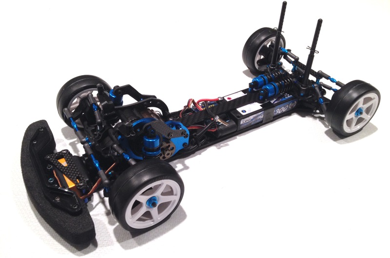
RtR weight with body: 1071g
After several days of driving the car and a comparison drive with my T4, I came to the conclusion that the front motor concept is working nice, but on ETS-carpet there is too much load on the front tires. And this costs a lot of agility. In comparison my T4'15 without rear belt has by far not enough pull out of the corner, but handles much better in the entry and middle corner part. In the end with the same tires my T4 13.5t in FWD mode was as fast as the FF03 with 10.5t.
So I constructed a chassis that not only makes the complicated plastic parts obsolete, but also allows a motor position in front and behind the front axle. Additionally I replaced the suspension parts with Xray hard parts and "active" rear (mostly to get rid of rear toe blocks).
I reduced the cog by taking away material from the gearbox mounts. This lowered this gearbox-motor unit around 3mm. I couldn't live with the motor hovering several millimeter above the chassis. I am also a big fan of lay down shocks. In the shown configuration only the rear shocks can "sleep". With the motor in front all shocks are horizontal
Tomorrow this thing will have its first shakedown


RtR weight with body: 1071g
Last edited by IAmGreatDane; 03-18-2017 at 03:00 PM. Reason: Grammer editing.

 03-19-2017, 10:56 AM
#2898
I am back from prototype testing
It was good! Even with the slower Volante (old version) tires and 17.5t motor (instead of Sorex 28 and 10.5t) I could match my fastest laptimes. I am very happy. The chassis has tons of steering and a much better corner entry. A lot of understeer also vanished in long fast corners. There the car pulls itself around the corner under full throttle. Very nice! The front now seems to have the right amount of load. I drove with 16lb/in springs all around, something I do with 4wd chassis and it worked perfectly. The car stays flat in the corner even without anti-roll-bars (I am going to install them next week). Also the nasty grip roll vanished.
I am very happy that this conversion works so nice. I had no problem all day, not even a loose screw (this must be the feeling Gordon Murray had after the first F1 race 1988)
03-19-2017, 02:02 PM
#2899
I am back from prototype testing
It was good! Even with the slower Volante (old version) tires and 17.5t motor (instead of Sorex 28 and 10.5t) I could match my fastest laptimes. I am very happy. The chassis has tons of steering and a much better corner entry. A lot of understeer also vanished in long fast corners. There the car pulls itself around the corner under full throttle. Very nice! The front now seems to have the right amount of load. I drove with 16lb/in springs all around, something I do with 4wd chassis and it worked perfectly. The car stays flat in the corner even without anti-roll-bars (I am going to install them next week). Also the nasty grip roll vanished.
I am very happy that this conversion works so nice. I had no problem all day, not even a loose screw (this must be the feeling Gordon Murray had after the first F1 race 1988)
It was good! Even with the slower Volante (old version) tires and 17.5t motor (instead of Sorex 28 and 10.5t) I could match my fastest laptimes. I am very happy. The chassis has tons of steering and a much better corner entry. A lot of understeer also vanished in long fast corners. There the car pulls itself around the corner under full throttle. Very nice! The front now seems to have the right amount of load. I drove with 16lb/in springs all around, something I do with 4wd chassis and it worked perfectly. The car stays flat in the corner even without anti-roll-bars (I am going to install them next week). Also the nasty grip roll vanished.
I am very happy that this conversion works so nice. I had no problem all day, not even a loose screw (this must be the feeling Gordon Murray had after the first F1 race 1988)
03-21-2017, 01:03 AM
#2901
This (and maybe) later posts will be about my FF03-conversion. After having received a lot of likes and positive reactions on my work (thank you very much!) I want to show details of what was needed to build this car and which extra parts I added. This way anyone interested knows what it takes if he likes to do this conversion himself.
First check the additonal parts needed:
1x Xray 306200-K - T4 2015 Alu Servo Mount - BLACK (2)
1x Xray servo saver #372503
1x Exotek 1495 F1 servo horn plate
2x Exotek 1397 F1R2 Servo mounts (used as rear bulkheads)
1x Tamiya 9805974 TB-02R posts 10.5mm
1x Tamiya 51457 TA-06 N-parts (rocker arm)
These parts plus my chassis parts will be enough to make a full conversion. Plus a lot of M3 shims
I (for the look) added a lot of blue parts (from the Pro version), the gear diff plus housing, DJCs and aluminium wheel hexes. And because I had so much spares from my T4`15, I used hard arms, C-hubs and hubs.
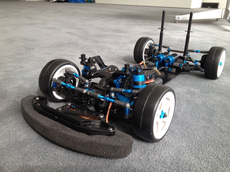
Lets take a closer look at the rear:
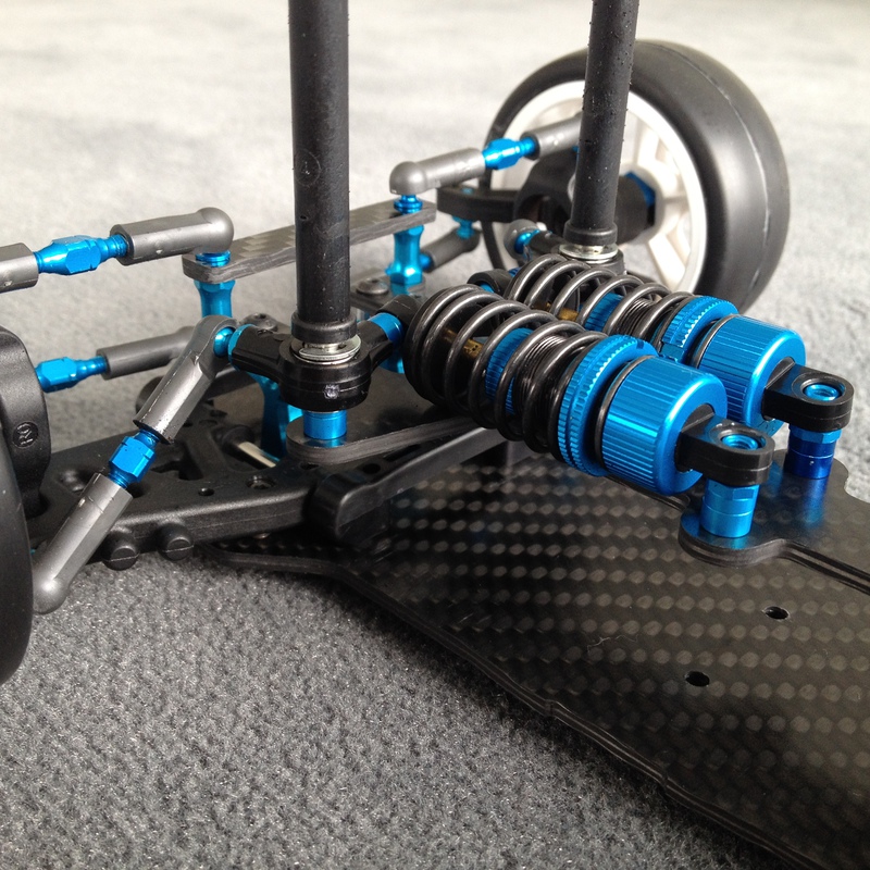
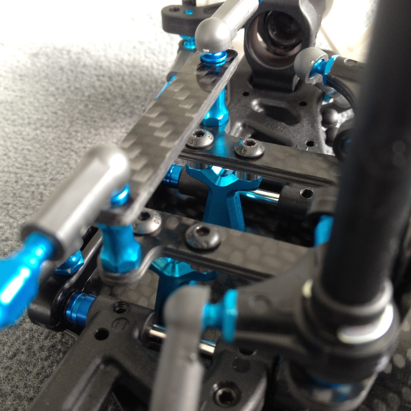
I went for lay down shocks, because I am just a big fan of it. Also it works pretty smooth with ball bearings and decent shimming in the rocker arms. The rocker arms and shock ends are attached to the top deck with counter sunk screws to have a low topdeck and to give the battery the opportunity to slide in sideways. As mentioned above the topdeck in the rear is attached to the chassis by Exotek F1 servo mounts. This is a low price, lightweight and for me practical solution as I had them laying around from my F1R2. So the topdeck is a multifunctional part including rocker-, shockposition and defining the camber links. I use a 1/12 sized 2s shorty lipo so my topdeck is just 19mm above the chassis plate. This would create arkward angles for the rear camber links. By using Tamiya 9805974 TB-02R posts I raised the ballstud position and strengthened the construction with a small carbon bridge connecting the ballstuds. Taking advantage of what is given harware wise, I used the upper open thread of the rocker nuts to attach the rear body posts (pan car style). Optional: The upside thread of the rear-rear-suspension block (1XD) is used for the active rear suspension style toe link ballstud. This way I could avoid buying Tamiya suspension blocks while having the advantage of a free toe adjustment. Depending on the rear arms used it is maybe necessary to drill holes for the rockerarm link and/or anti-roll-bar-mount.
These are all "secrets" in the rear. A lot of text, but mostly plug and play in the end.
Lets see what happens in front.

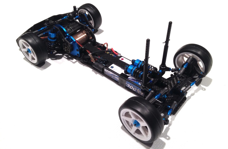
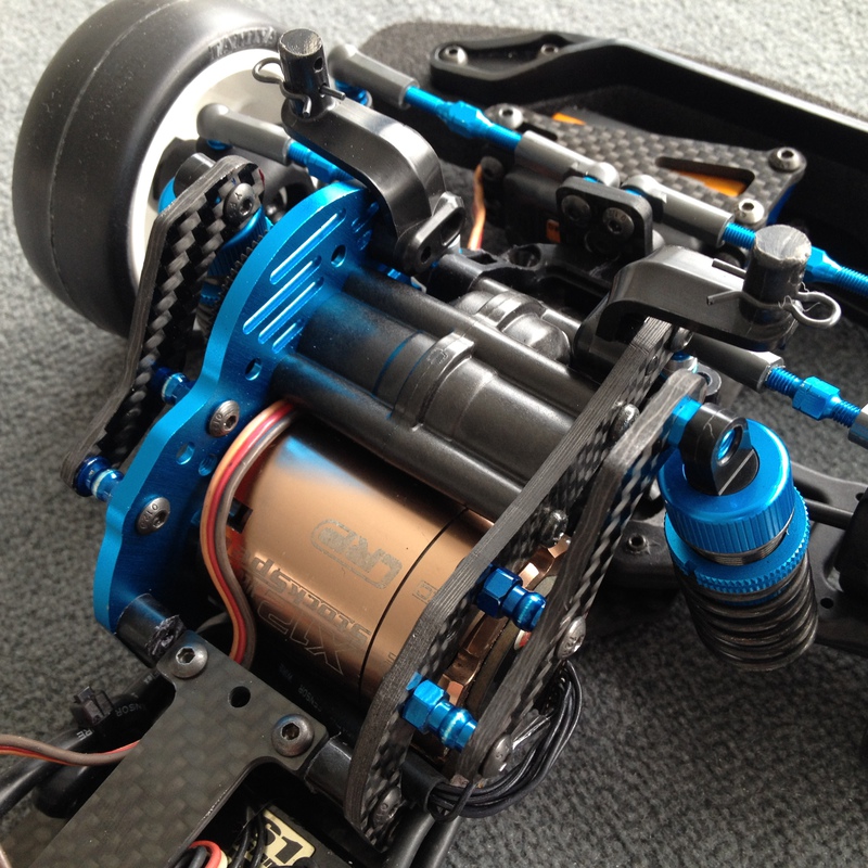
The layout of the lower chassis plate allows for two motor positions: The "traditional" motor position and the front middle motor position (as shown here). If you go for the "traditional" position the standard steering layout can be used. The front shocks will have a lay down position.
The front middle motor layout does not have enough space for that. The shocks are in an standing position and attached to the aluminum motor plate and the motor mount on the left side via small carbon parts. The front end of the topdeck has three holes to attach it to the M1-part (51422 M-parts from your FF03). This part has to be optimized to make space. In the end I used the outer two hole for attachment only. Also this part has to be shimmed out correctly for a straight attachment to the lower chassis as the bumper now doesn't fill the space in between (see FF03 manual).
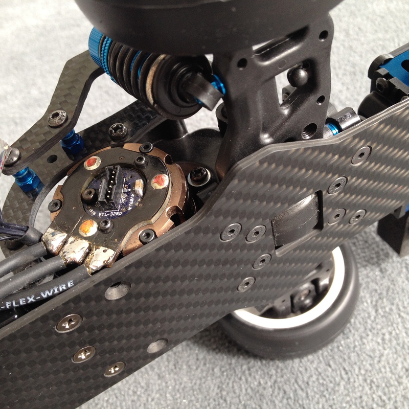
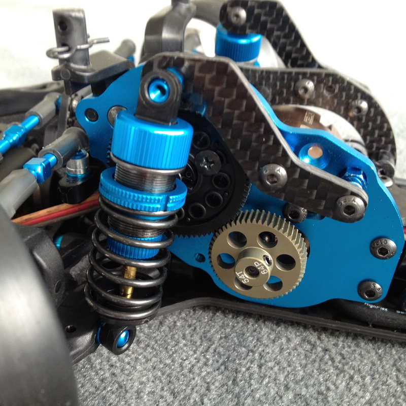
Now a mod for the hardcore racer (optional): After first installing the gearbox on the prototype (flat) chassis I discovered that the motor hovered nearly 3mm above the chassis Not sure why Tamiya constructed it this way, but I couldn't let this happen. The easiest way to reduce the height is to precisely cut away the lower tabs of the gearbox. And that is what I did. If you do it take your time and check that the cut is straight and/or file away the last half millimeter to make it perfect. You can do it without being a pro just take time and check several times. The carbon chassis already features a large enough cut out for the lower differential housing.
Everything else is plug and play (servo mounting with Xray alu servo mount --> picture shows a TC6.2 servo mount, suspension, body posts...). Just the bumper will need some material removal to not collide with the servo (low profile please ). You can shim the servo upward if you don't want to modify the bumperbase.

Ok, now there is one thing, which nearly killed this project for me. And I thought I could not come up with a solution. But looking at this problem now, it wasn`t a problem at all and even gave me a deeper understanding about sensored brushless motors. What am I blabbering about ( ) is that with the front-middle-motor-configuration we turned the motor around 180�. So it turns in the wrong direction. For unsensored and brushed motors this is not a problem. Just switch plus and minus cables or A & C. But a sensored motor will not turn with just changing cable position or the esc will even tell you there is a problem and do nothing. There are three steps to make a sensored brushless motor of any make switch its rotating direction:
1. Switch cable position A & C on the motor side
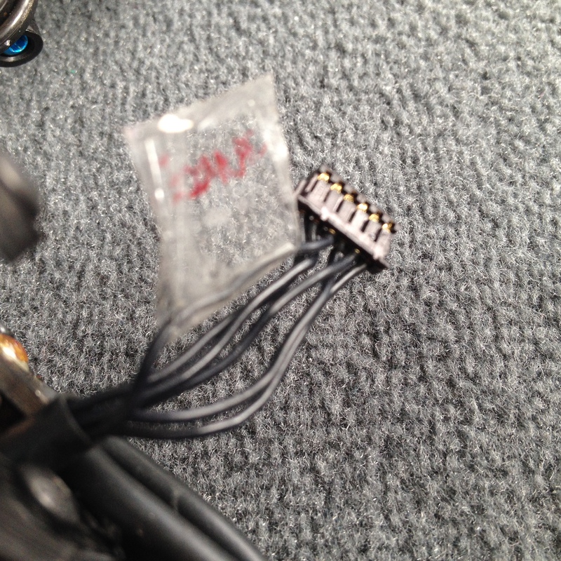
2. Switch sensor cable pin position: pin #2 with pin #4 on the motor side. Don't be afraid here. Just count the wires from left to right. If you did it wrong nothing will happen. Then bring it back in the original order and just count from the other side and voil� it works! Just don't change the most outter pins: pin #1 with pin #6 that is plus and minus
Here is an overview:
Pin#1 - ground potential (minus)
Pin#2 - sensor phase C
Pin#3 - sensor phase B
Pin#4 - sensor phase A
Pin#5 - motor temperature sensing
Pin#6 - sensors feeding +5.0V
3. Now only the timing could create a problem (LRP for example has already 30� fixed timing build in). So only if the motor will not turn even if the esc says everything is ok, then take out the timing insert and turn it one step into the desired turning direction and push it back in (for LRP there are three slots for the inner insert, I guess this is for every motor the same). For motors with true 0� timing try to adjust how you normally do it, just in the other direction. Now the motor is ready to race. Without pinion you can check under full throttle how the timing changes the revs. Pretty cool Just don't be afraid! You can not destroy anything here and it is completly reverseable. Motor and esc are not at risk here.
I tell you, I felt like Hackerman after this worked out on the second try (had to come up with most of it myself...)
I can offer the front-middle-motor carbon parts (topdeck, chassis, front shock stays and rear link brace) in high quality for 105� plus shipping in a very limited number. If someone is interested please start a list here.
Please note that if the motorposition is changed to the original layout you would need a new topdeck; and I didn't work on the servo and electronics attachment in the traditional layout, yet!
If there are unclear chapters or you have questions of every kind. Feel free to ask!

First check the additonal parts needed:
1x Xray 306200-K - T4 2015 Alu Servo Mount - BLACK (2)
1x Xray servo saver #372503
1x Exotek 1495 F1 servo horn plate
2x Exotek 1397 F1R2 Servo mounts (used as rear bulkheads)
1x Tamiya 9805974 TB-02R posts 10.5mm
1x Tamiya 51457 TA-06 N-parts (rocker arm)
These parts plus my chassis parts will be enough to make a full conversion. Plus a lot of M3 shims
I (for the look) added a lot of blue parts (from the Pro version), the gear diff plus housing, DJCs and aluminium wheel hexes. And because I had so much spares from my T4`15, I used hard arms, C-hubs and hubs.
Lets take a closer look at the rear:


I went for lay down shocks, because I am just a big fan of it. Also it works pretty smooth with ball bearings and decent shimming in the rocker arms. The rocker arms and shock ends are attached to the top deck with counter sunk screws to have a low topdeck and to give the battery the opportunity to slide in sideways. As mentioned above the topdeck in the rear is attached to the chassis by Exotek F1 servo mounts. This is a low price, lightweight and for me practical solution as I had them laying around from my F1R2. So the topdeck is a multifunctional part including rocker-, shockposition and defining the camber links. I use a 1/12 sized 2s shorty lipo so my topdeck is just 19mm above the chassis plate. This would create arkward angles for the rear camber links. By using Tamiya 9805974 TB-02R posts I raised the ballstud position and strengthened the construction with a small carbon bridge connecting the ballstuds. Taking advantage of what is given harware wise, I used the upper open thread of the rocker nuts to attach the rear body posts (pan car style). Optional: The upside thread of the rear-rear-suspension block (1XD) is used for the active rear suspension style toe link ballstud. This way I could avoid buying Tamiya suspension blocks while having the advantage of a free toe adjustment. Depending on the rear arms used it is maybe necessary to drill holes for the rockerarm link and/or anti-roll-bar-mount.
These are all "secrets" in the rear. A lot of text, but mostly plug and play in the end.
Lets see what happens in front.


The layout of the lower chassis plate allows for two motor positions: The "traditional" motor position and the front middle motor position (as shown here). If you go for the "traditional" position the standard steering layout can be used. The front shocks will have a lay down position.
The front middle motor layout does not have enough space for that. The shocks are in an standing position and attached to the aluminum motor plate and the motor mount on the left side via small carbon parts. The front end of the topdeck has three holes to attach it to the M1-part (51422 M-parts from your FF03). This part has to be optimized to make space. In the end I used the outer two hole for attachment only. Also this part has to be shimmed out correctly for a straight attachment to the lower chassis as the bumper now doesn't fill the space in between (see FF03 manual).


Now a mod for the hardcore racer (optional): After first installing the gearbox on the prototype (flat) chassis I discovered that the motor hovered nearly 3mm above the chassis
Not sure why Tamiya constructed it this way, but I couldn't let this happen. The easiest way to reduce the height is to precisely cut away the lower tabs of the gearbox. And that is what I did. If you do it take your time and check that the cut is straight and/or file away the last half millimeter to make it perfect. You can do it without being a pro just take time and check several times. The carbon chassis already features a large enough cut out for the lower differential housing.Everything else is plug and play (servo mounting with Xray alu servo mount --> picture shows a TC6.2 servo mount, suspension, body posts...). Just the bumper will need some material removal to not collide with the servo (low profile please
). You can shim the servo upward if you don't want to modify the bumperbase.
Ok, now there is one thing, which nearly killed this project for me. And I thought I could not come up with a solution. But looking at this problem now, it wasn`t a problem at all and even gave me a deeper understanding about sensored brushless motors. What am I blabbering about (
) is that with the front-middle-motor-configuration we turned the motor around 180�. So it turns in the wrong direction. For unsensored and brushed motors this is not a problem. Just switch plus and minus cables or A & C. But a sensored motor will not turn with just changing cable position or the esc will even tell you there is a problem and do nothing. There are three steps to make a sensored brushless motor of any make switch its rotating direction:1. Switch cable position A & C on the motor side
2. Switch sensor cable pin position: pin #2 with pin #4 on the motor side. Don't be afraid here. Just count the wires from left to right. If you did it wrong nothing will happen. Then bring it back in the original order and just count from the other side and voil� it works! Just don't change the most outter pins: pin #1 with pin #6 that is plus and minus
Here is an overview:
Pin#1 - ground potential (minus)
Pin#2 - sensor phase C
Pin#3 - sensor phase B
Pin#4 - sensor phase A
Pin#5 - motor temperature sensing
Pin#6 - sensors feeding +5.0V

3. Now only the timing could create a problem (LRP for example has already 30� fixed timing build in). So only if the motor will not turn even if the esc says everything is ok, then take out the timing insert and turn it one step into the desired turning direction and push it back in (for LRP there are three slots for the inner insert, I guess this is for every motor the same). For motors with true 0� timing try to adjust how you normally do it, just in the other direction. Now the motor is ready to race. Without pinion you can check under full throttle how the timing changes the revs. Pretty cool
Just don't be afraid! You can not destroy anything here and it is completly reverseable. Motor and esc are not at risk here.I tell you, I felt like Hackerman after this worked out on the second try (had to come up with most of it myself...)
I can offer the front-middle-motor carbon parts (topdeck, chassis, front shock stays and rear link brace) in high quality for 105� plus shipping in a very limited number. If someone is interested please start a list here.
Please note that if the motorposition is changed to the original layout you would need a new topdeck; and I didn't work on the servo and electronics attachment in the traditional layout, yet!
If there are unclear chapters or you have questions of every kind. Feel free to ask!
Last edited by wtcc; 03-21-2017 at 05:28 AM.
03-21-2017, 08:55 AM
#2903
Right now I am planning to use the K-parts 12 to 14 and put them on the suspension block for the rear and on the gear box in front.
If nothing else comes in the way I try it tomorrow.
If nothing else comes in the way I try it tomorrow.
03-22-2017, 09:38 AM
#2904
This car build is on the finish straight.
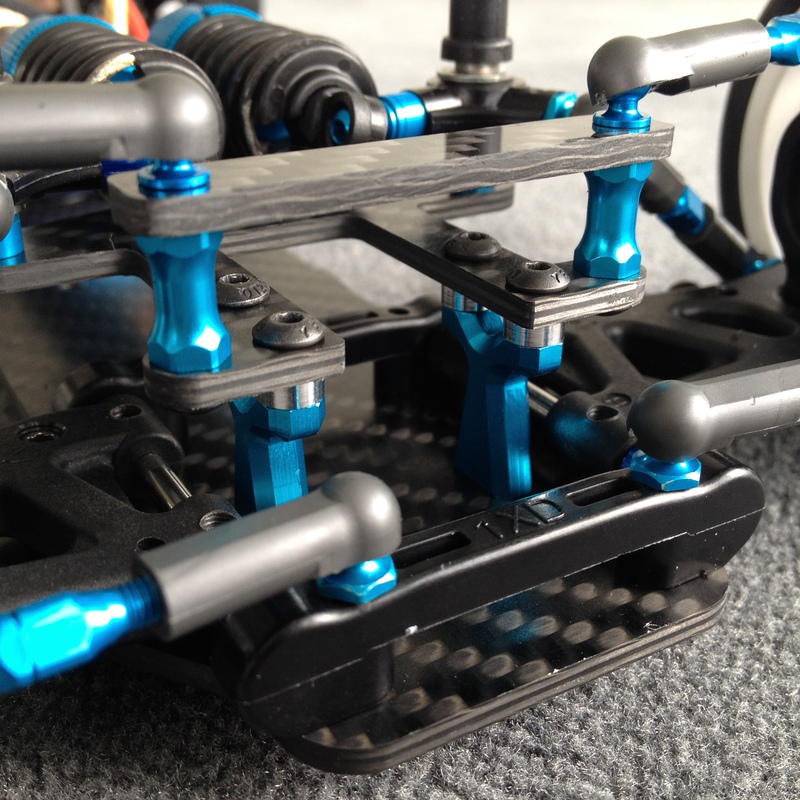
Today I found time to implement the front anti-roll-bar. In the planning stage it was quite frustrating. There are so many things to check and think about to prevent collision with other parts. I found a good space and it worked with the angles of the anti-roll-bar-wire. It was inevitable to build another small carbon plate as base for the K-part. In fact I had two ideas on my mind for this base and decided for the more easy to dremel one (yes all small carbon parts are handmade, only chassis and topdeck were milled, not by me). Unfortunately everything assembled was one millimeter to high and collided with the servo arm I had no choice but to build the base from my second idea which is also a replacement for the servo mount plate.


Building carbon parts by hand is always a little gamble as it is not easy at all to precisely drill the holes. But I was lucky here and hit the marks well. While I was wearing all protection gear I copied two Tamiya tuning parts that replace the upper bumper brace. That mod really looks good
Today I found time to implement the front anti-roll-bar. In the planning stage it was quite frustrating. There are so many things to check and think about to prevent collision with other parts. I found a good space and it worked with the angles of the anti-roll-bar-wire. It was inevitable to build another small carbon plate as base for the K-part. In fact I had two ideas on my mind for this base and decided for the more easy to dremel one (yes all small carbon parts are handmade, only chassis and topdeck were milled, not by me). Unfortunately everything assembled was one millimeter to high and collided with the servo arm
I had no choice but to build the base from my second idea which is also a replacement for the servo mount plate.

Building carbon parts by hand is always a little gamble as it is not easy at all to precisely drill the holes. But I was lucky here and hit the marks well. While I was wearing all protection gear I copied two Tamiya tuning parts that replace the upper bumper brace. That mod really looks good
03-22-2017, 09:59 AM
#2905
Very very nice!
03-23-2017, 05:57 AM
#2906
Yea good work. I always liked custom built cars.
03-23-2017, 10:29 AM
#2907
WTCC, can you please tell me the part number for the sway bar mounts that sit on your custom made small support right in front of the carbon servo mount? Thanks!
03-23-2017, 11:36 AM
#2908
That is part K14 with K12 & K13 as upper "slop remover"
K-parts of FF03 are Tamiya number 19115284.
I removed the "ears" of each side to make a flat underside and drilled two more inner holes (2,5mm) to attach it to the carbon servo plate.
K-parts of FF03 are Tamiya number 19115284.
I removed the "ears" of each side to make a flat underside and drilled two more inner holes (2,5mm) to attach it to the carbon servo plate.
03-23-2017, 02:30 PM
#2909
As usual I love your project wtcc! I was skeptical of the overhanging motor too, so a few years ago I snatched one of the last TOP Sabre FD that I could find new. I built it but never got around to running it . Your car looks a thousand times cooler though. Looking forward to seeing what you are going to do next.
. Your car looks a thousand times cooler though. Looking forward to seeing what you are going to do next.
03-24-2017, 03:55 AM
#2910
Great build. Way above my skill set.
Have you thought about swapping the battery and electronics around? Moving the weight forward a little.
Have you thought about swapping the battery and electronics around? Moving the weight forward a little.