


 715Likes
Touring by h2e (1/10th, 190mm, 4wd)


 12-30-2020, 07:20 AM
#48
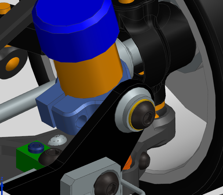
Shock mounting on shock tower - overview of parts
Cutaway view of parts.
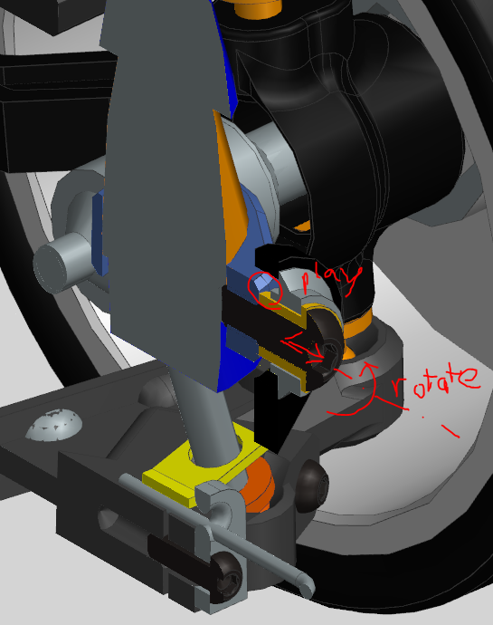
I am also considering a ballhead style mounting:
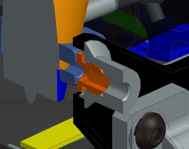
Orange ballhead mounted to shock clamp (light blue). This way, the shock pivot is off-axis, but with the clamp, motion is limited.
12-31-2020, 02:48 AM
#50
Hi RCtech Forum, I thought I'd share one last series of images of the h2e touring car progress. 3D printing even parts of the chassis helped tremendously to sort out errors, get a feeling for the serviceability and adjustability of the future car.
Leaf spring system and view of bulkheads.
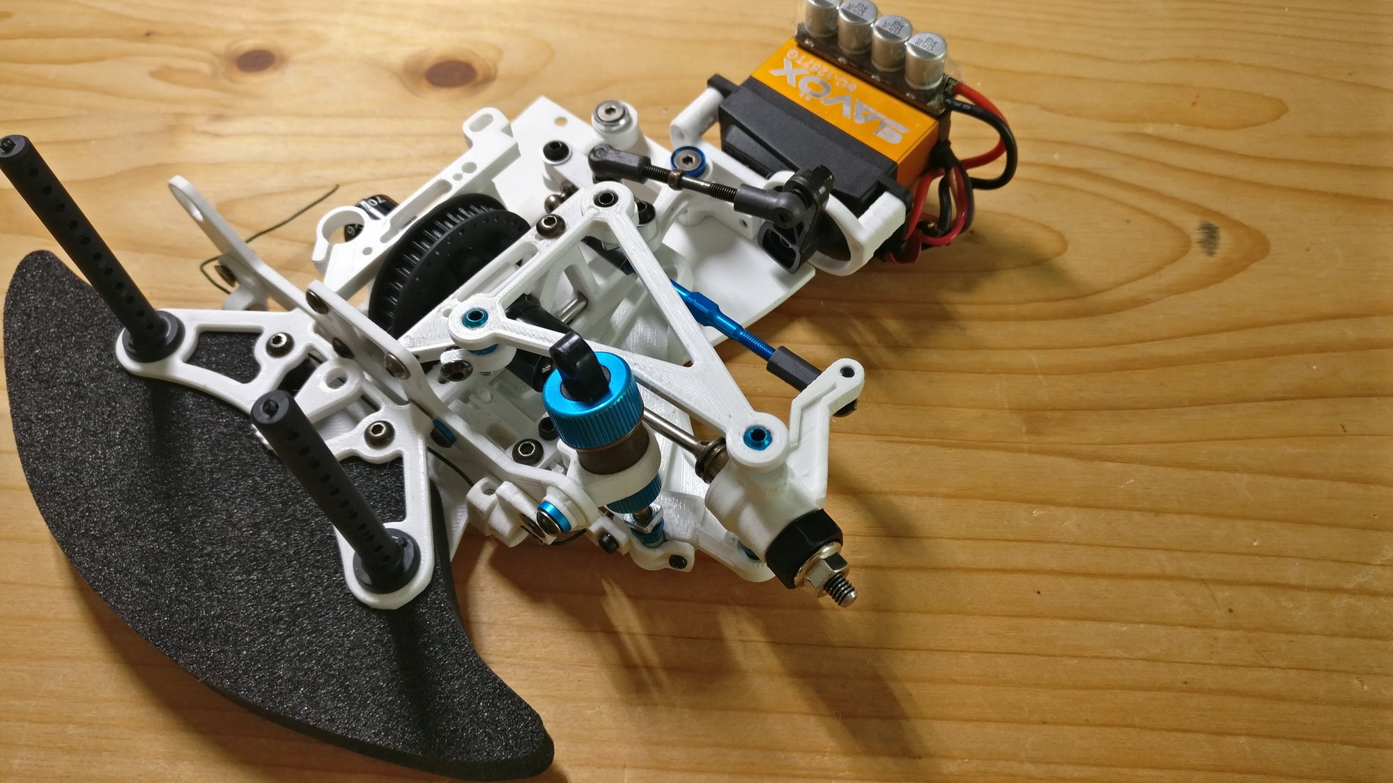
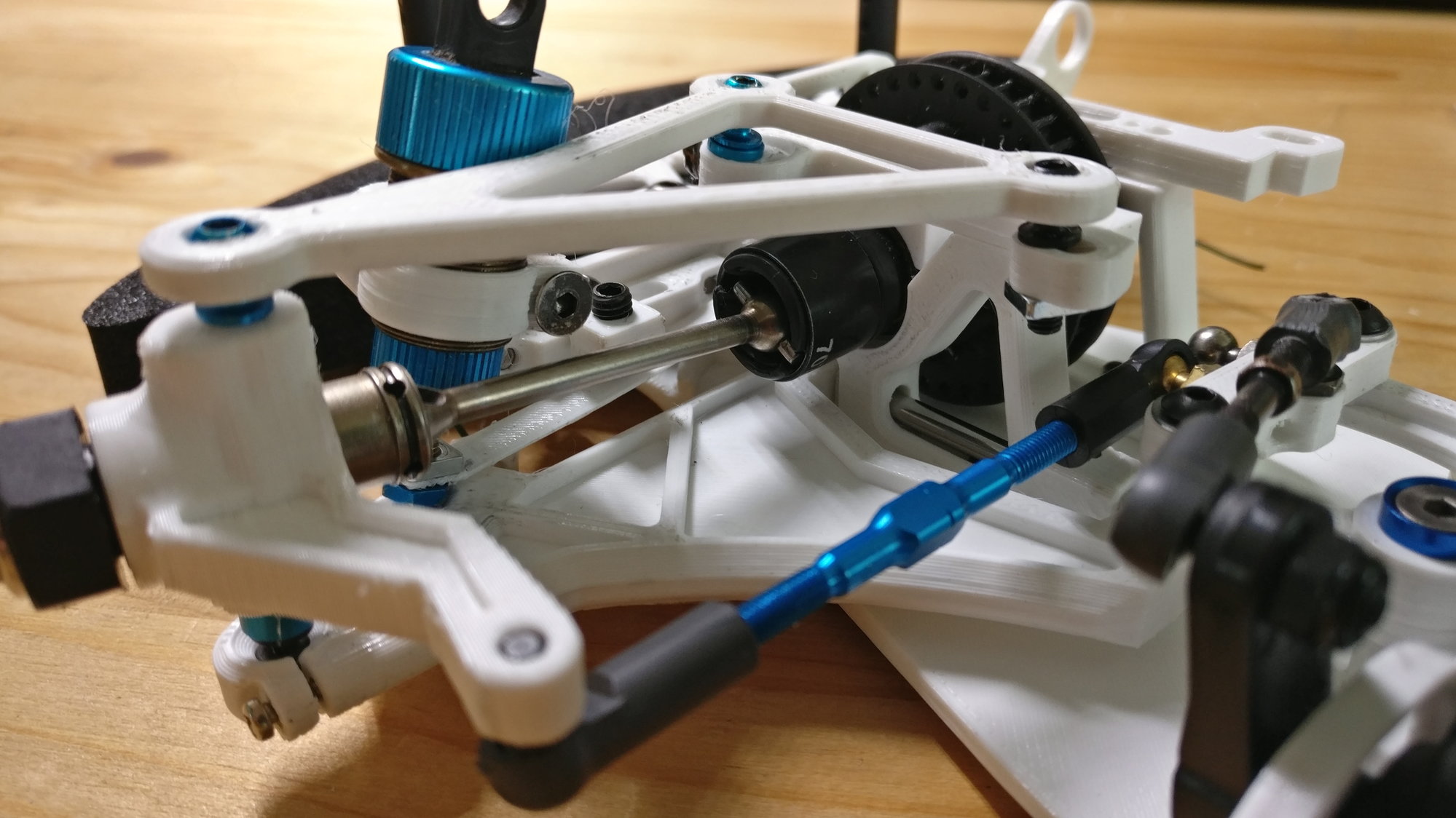
Front left corner overview with steering assembly.
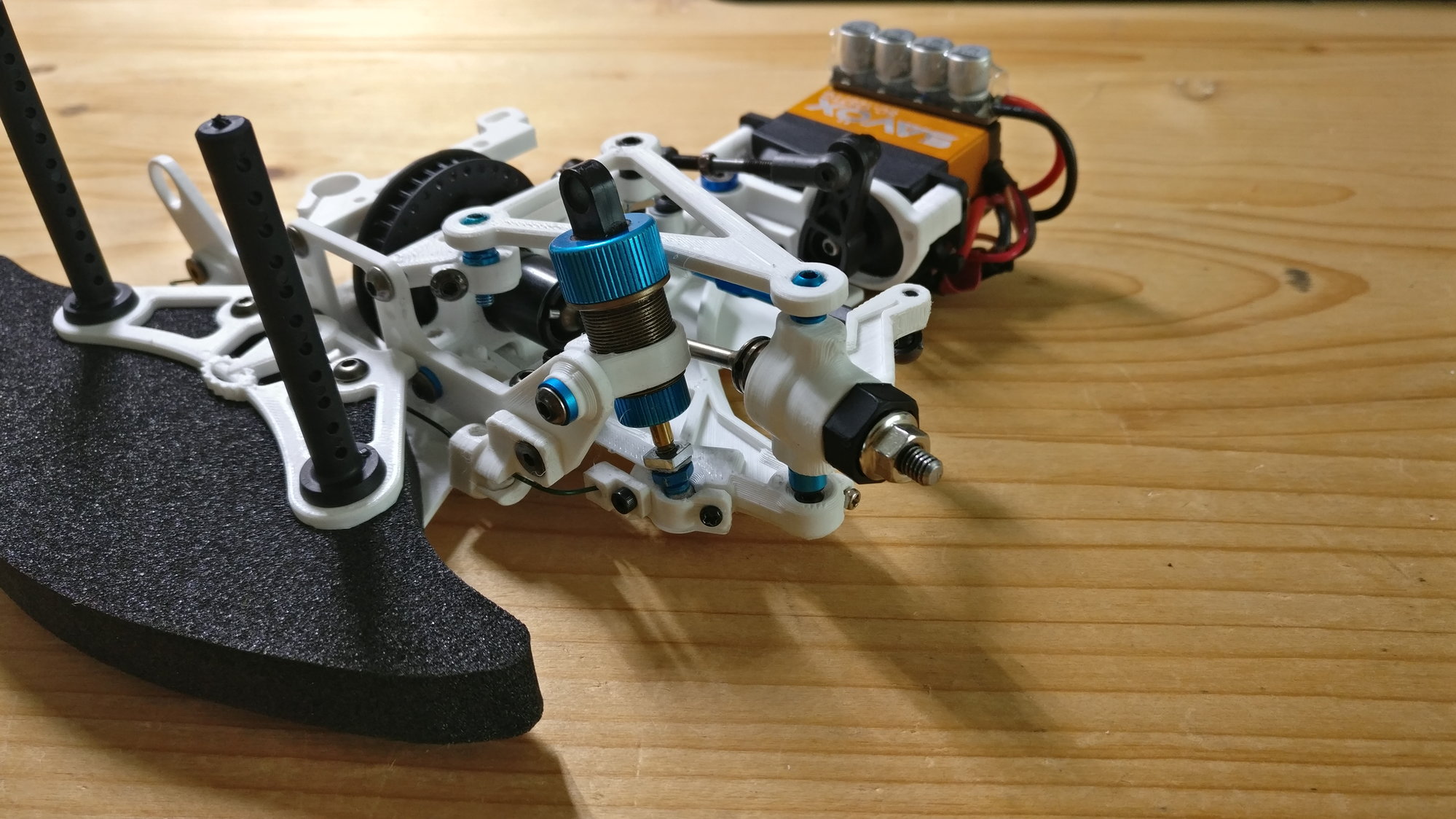
ARB mounting still experimental, but basics can be seen.
And by the way. Happy new year to you all.
Leaf spring system and view of bulkheads.
Front left corner overview with steering assembly.
ARB mounting still experimental, but basics can be seen.
And by the way. Happy new year to you all.
12-31-2020, 06:39 AM
#51
I believe your shock tower is a bit thin, it looks like 2mm to me. I'd want that to be 4mm material, but at minimum, at least match what's out there? The short distance from shock pivot to the mount is going to put more than the usual torque on that.
.... we'll see if I'm up to doing calculations later.
Having springy/bouncy shock towers isn't.. nice. As it puts a spring in the middle of your damping system. That's a hard system to chase down. In an extreme example, my DT-02 will do a complete bounce off the ground, based on shock tower flex before the shocks can do their job.
I do like watching you build this thing :-)
12-31-2020, 12:56 PM
#52
Yeah, the ARB will be another quest. You can take a look at my solution for my TT02 KR v2.5.
12-31-2020, 05:08 PM
#53
I believe your shock tower is a bit thin, it looks like 2mm to me. I'd want that to be 4mm material, but at minimum, at least match what's out there? The short distance from shock pivot to the mount is going to put more than the usual torque on that.
.... we'll see if I'm up to doing calculations later.
Having springy/bouncy shock towers isn't.. nice. As it puts a spring in the middle of your damping system. That's a hard system to chase down. In an extreme example, my DT-02 will do a complete bounce off the ground, based on shock tower flex before the shocks can do their job.
I do like watching you build this thing :-)
.... we'll see if I'm up to doing calculations later.
Having springy/bouncy shock towers isn't.. nice. As it puts a spring in the middle of your damping system. That's a hard system to chase down. In an extreme example, my DT-02 will do a complete bounce off the ground, based on shock tower flex before the shocks can do their job.
I do like watching you build this thing :-)
I intend to go full prototype alu and carbon, as soon as I am happy with the design and you folks have no big questionmarks unanswered.
12-31-2020, 05:14 PM
#54
BTW Ahltec doesn't seem to sell 2.25mm carbon plates? Do you not use that on your projects?
01-01-2021, 09:45 AM
#55
Funny you mentioned the shock tower! As I had it printed out I realized that it flexes too much forward, aka torsion, due to the larger offset force. Damper effectiveness is good, with a larger motion ratio than normal, but it's eaten by the weak shocktower. Yes in the model it was only 2.25mm. Now I am at 3mm. 4 wasn't possible due to the bumper.
I intend to go full prototype alu and carbon, as soon as I am happy with the design and you folks have no big questionmarks unanswered.
I intend to go full prototype alu and carbon, as soon as I am happy with the design and you folks have no big questionmarks unanswered.
and .. it'll look cool.
01-01-2021, 01:11 PM
#56
Importantly, that makes your shock tower a spring, and not one you can easily charecterize. that is no bueno. :-) 4 you can do if you machine it down a bit. Or maybe... make a biplane tower? Hmm.... I'll do a drawing tonight. A biplane tower would allow you to go wiht like 1mm plates and get much more stiffness for the same weight.
and .. it'll look cool.
and .. it'll look cool.
01-06-2021, 11:58 PM
#57
Thought I'd share some rather unique insight into designing an RC car: Full FE-Analysis of a corner.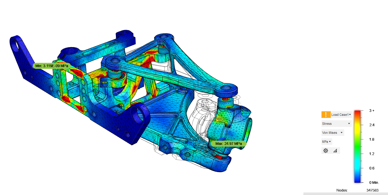
Von Mises Stress for 10N load (facing - car travel) acting at outer wheel bearing center. The red spots exhibit more than 3MPa (which is super low).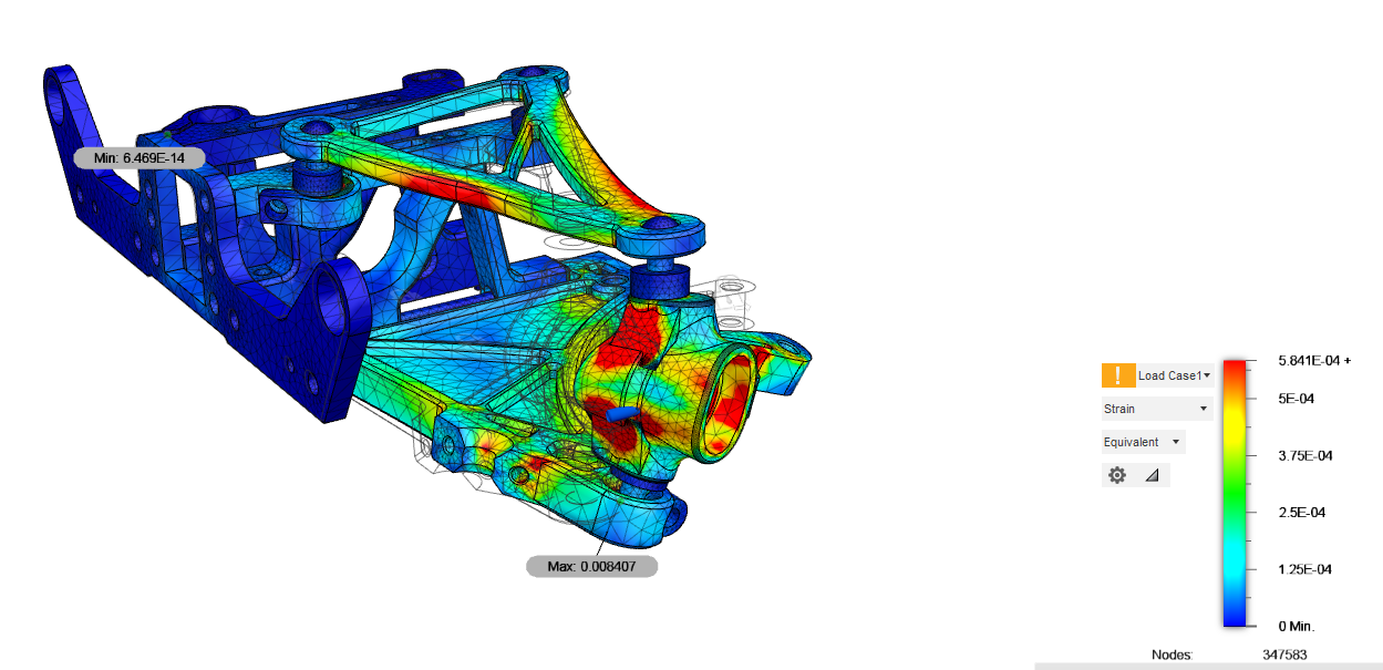
FL corner Strain (aka local deformation) for same load case.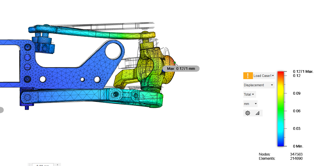
Displacement seen from front - scaled to be 5% of model size for visibility.
- All parts are connected via sliding or sticking contacts, where appropriate
- All materials are as intended in the future: ABS, Aluminium and 3mm Carbon quasi-isotropic.

Material designation of front corner: Black: ABS Plastic, Blue: Aluminium high strength, Weaved: Carbon fibre, grey: Steel - I already beefed up some areas, where strain was really high.
Von Mises Stress for 10N load (facing - car travel) acting at outer wheel bearing center. The red spots exhibit more than 3MPa (which is super low).
- The filled area between the stiffening ribs of the lower wishbone is not highly stressed. Nevertheless, it is responsible for increasing the overall stiffness and worth the weight penalty in my view.
- The bulkhead top (holding the diff) is one of the higher stressed parts. Due to its mounting and offset loading, that was to be expected. Nevertheless, some strengthening changes could be applied.
- Some of the deformation from this load case is transferred to the opposite bulkhead, so the carbon shock tower is definitely a stiffness aid.
FL corner Strain (aka local deformation) for same load case.
- The upper wishbone is showing the largest strains. I played around with the stiffening rib a bit, only to find, that a "similar to Mugen MTC2" design was the stiffest and lightest. Only that I don't have an outer turnbuckle - saving some valuable unsprung mass

- Also visible are the relatively high strains around the two ballhead screws of the steering knuckle. This might be a reason why some brands use aluminium parts for these?
Displacement seen from front - scaled to be 5% of model size for visibility.
- The upper bulkhead bends down on the front balljoint. Also, the steering knuckle is being warped due to the loading.
- Overall, the suspension roughly has a stiffness of 50N/mm in the longitudinal direction. I consider this rather stiff compared to Tamiya suspensions. So it seems, play of the ballheads is more important than stiffness of the parts.
01-07-2021, 07:39 AM
#58
Well after the science rush this morning, I thought I would add one more piece of information. I built a small measurement rack to evaluate bulkhead to bulkhead torsion stiffness:
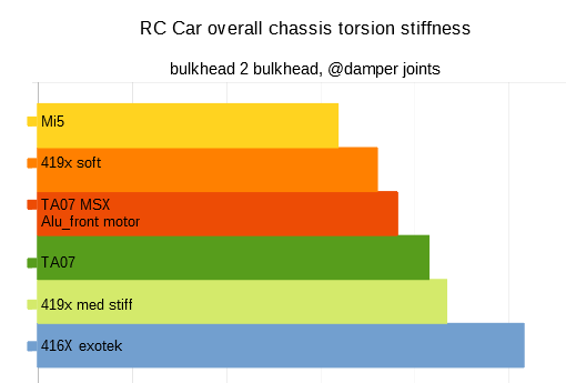
RC Onroad Chassis torsion stiffness [Nm/rad] for different cars.
The Mi5 is from Schumacher, all other cars are Tamiya. The 416X is with an exotek "soft chassis". 419x med stiff is with the motormount stiffener added. TA07 is my RClabHK carbon version, 419x soft is without the motormount front bolt, and no topdeck post.
01-11-2021, 08:36 AM
#59
Awesome insights here!
Unfortunately I cannot discuss with you, because I don’t know how my TT02 conversion deforms under stress. I just know that it lasts. The only thing that broke was a rear bodypost after a heavy impact. All the my parts will guide the forces into the (poor) TT02 chassis and kill the threads of the lower droop plate over time.
Because of the Ahltec carbon I only use 2mm/2.5mm/3mm/4mm carbon plates for my parts.
You can try SNZ Schneidebetrieb GmbH. They only do water jet cutting as far as I know, but are close to aircraft- and motorsport-industry and have more carbon fiber variations with better strength and quality to choose from than we are used to in R/C.
01-12-2021, 01:08 AM
#60
Tech Addict
H2e seems like the guy that can help you in explaining and more on how you measure the stiffness. Would be interesting for sure.