


 424Likes
wtcc's FF project


 11-01-2017 | 03:23 PM
#18

@G-rem: Accurate drawings, then I drill the holes with self-centering-drills. The last step is to cut and shape after the outlines... Important is to check accurately the geometry and that you hit the marks as good as possible. Then slowly drill, making sure that the drill is not pushed off track by the weave of the cfk.
@Laguna Bozo:Thank you very much!!!
@aracefan: Here some pictures of my little "fridge":
Bilster Berg:

Nuerburgring Nordschleife:
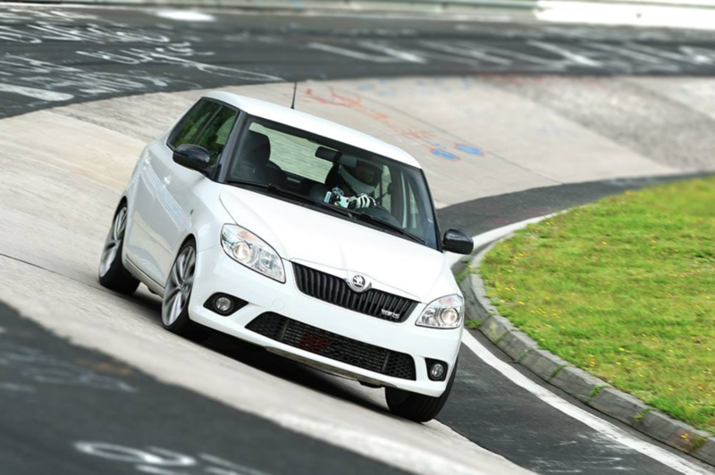

1200Kg, 190Ps, 7 speed DKG
@Laguna Bozo:Thank you very much!!!
@aracefan: Here some pictures of my little "fridge":
Bilster Berg:

Nuerburgring Nordschleife:


1200Kg, 190Ps, 7 speed DKG
Last edited by wtcc; 11-01-2017 at 03:35 PM.
11-02-2017 | 01:11 PM
#19
My spare- and tuningparts came today. I was so excited! Finally the car will have the right width and be back in one piece 
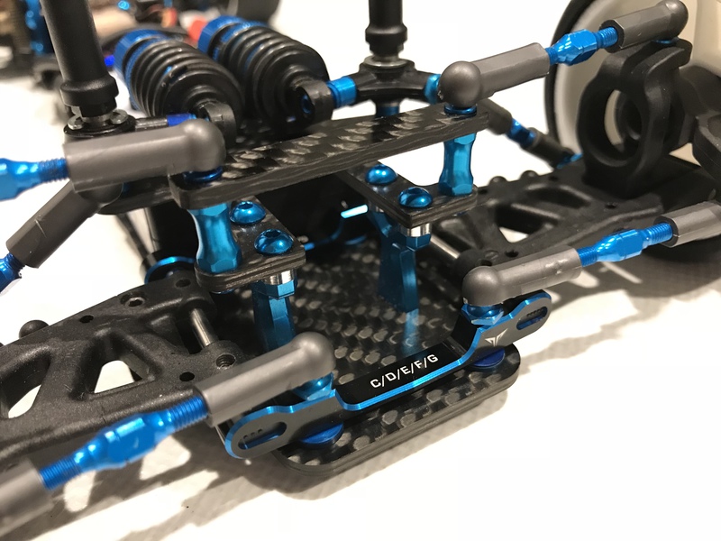
These Techra mounts look so good
But then the RC reality hit "hard". The front drive shafts are too short Now I can't drive the car on the weekend
  Luckily I come away with "just" 17,99� for the 46mm shafts for the #42216 DCJs...

These Techra mounts look so good
But then the RC reality hit "hard". The front drive shafts are too short
Now I can't drive the car on the weekend Luckily I come away with "just" 17,99� for the 46mm shafts for the #42216 DCJs...
11-03-2017 | 04:07 AM
#20
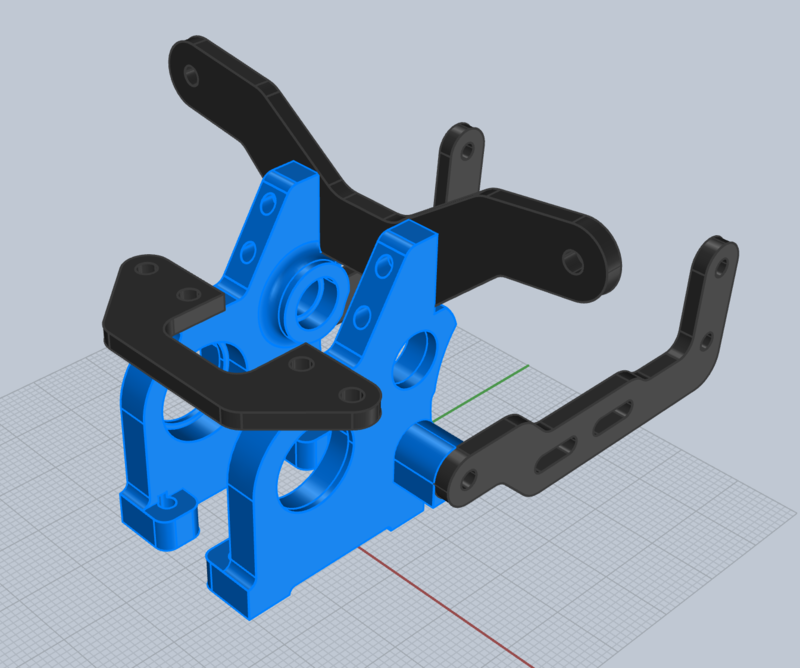
Now that the car is repaired, I checked my measurements with the cad file.
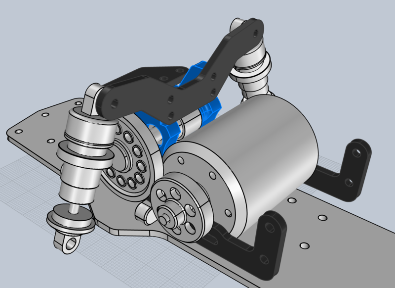
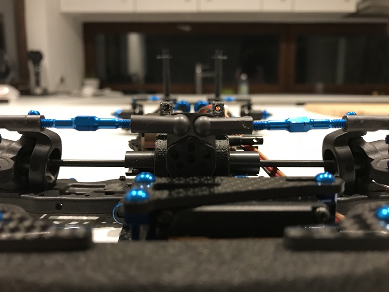
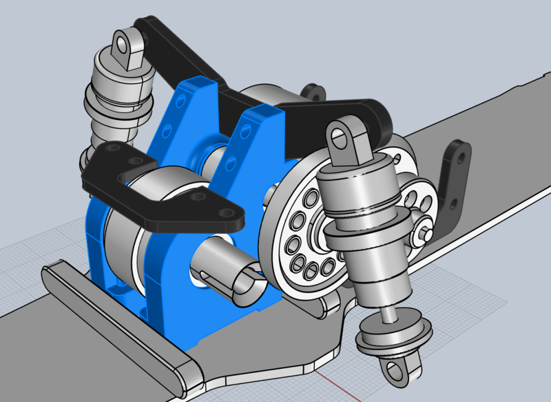
I couldn't find a mistake, but together with the "DCJ incident" I was remembered of the ugly angles of the DCJ between differential and hub. As it is right now, the differential is placed very low. Even without load on the car, they are severely angled up. Additionally they are also angled backwards. Because of the doublejoints there is no shattering or other problems occuring...
Yet, every constructor of 1:1 racecars tries to achieve the smallest possible shaft angles between gearbox and hub. A comparison with the T4'17 showed that the center of its spool is around 19mm above the chassisplate. That is what I copied for the FF03r gear differential.
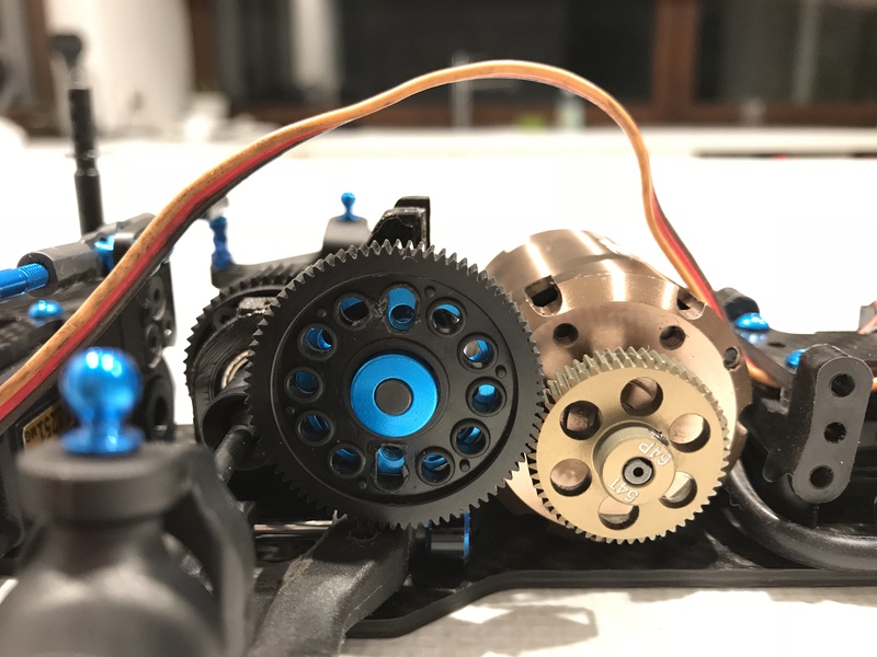
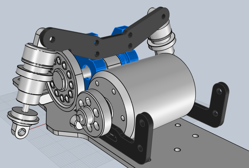
It was one of these rare moments, where with one decision suddenly everything went in the right direction. This position change together with the small Techra mounts solved several major and minor problems Now I have not only nearly nullified the DCJ angles, but could also lower the spur-/countergear-unit, gained space for the motormovement (for different gearing), now totally avoid a possible collision between spur and axle and could position the shocktower in a perfect place. The whole bulkhead-unit is together with the shocktower and camberlink-brace compact & stable. Something that is welcomed, as the printed bulkheads could need it. All this for a 5mm higher placed geardiff.
I couldn't find a mistake, but together with the "DCJ incident" I was remembered of the ugly angles of the DCJ between differential and hub. As it is right now, the differential is placed very low. Even without load on the car, they are severely angled up. Additionally they are also angled backwards. Because of the doublejoints there is no shattering or other problems occuring...
Yet, every constructor of 1:1 racecars tries to achieve the smallest possible shaft angles between gearbox and hub. A comparison with the T4'17 showed that the center of its spool is around 19mm above the chassisplate. That is what I copied for the FF03r gear differential.
It was one of these rare moments, where with one decision suddenly everything went in the right direction. This position change together with the small Techra mounts solved several major and minor problems
Now I have not only nearly nullified the DCJ angles, but could also lower the spur-/countergear-unit, gained space for the motormovement (for different gearing), now totally avoid a possible collision between spur and axle and could position the shocktower in a perfect place. The whole bulkhead-unit is together with the shocktower and camberlink-brace compact & stable. Something that is welcomed, as the printed bulkheads could need it. All this for a 5mm higher placed geardiff. 


 I always thought that this solution would be better and more efficient than standart buggy gearbox
11-07-2017 | 11:33 AM
I always thought that this solution would be better and more efficient than standart buggy gearbox
11-07-2017 | 11:33 AM
#23
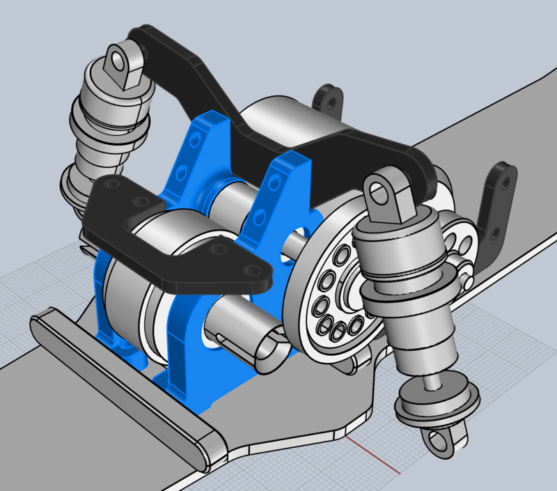
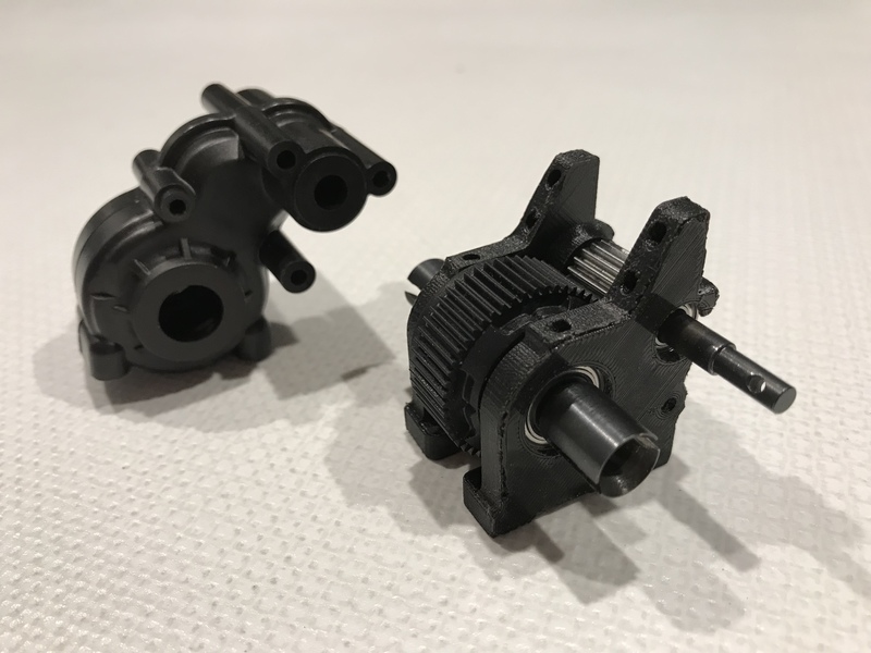
Prototyping begins!
I printed both bulkheads and installed them. Seating of the ballbearing could be better. They didn't went in without grinding. Even the screwholes needed a 2.5mm drill. Unfortunately I was to optimistic with the low position of the spur gear. I need to move it up 2mm to get clearance for the a-arm under load. Here now some first pictures:
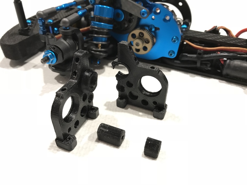
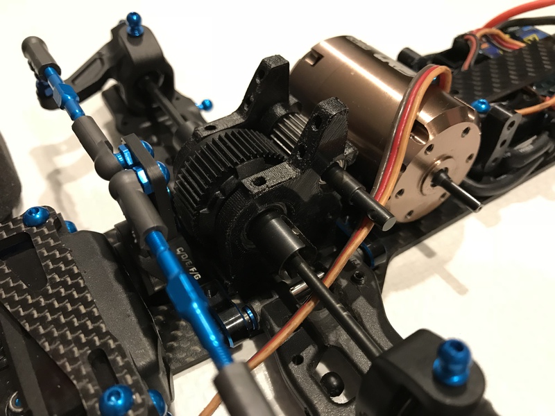
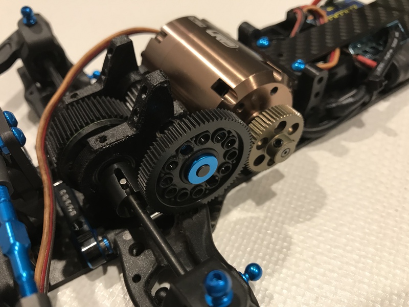
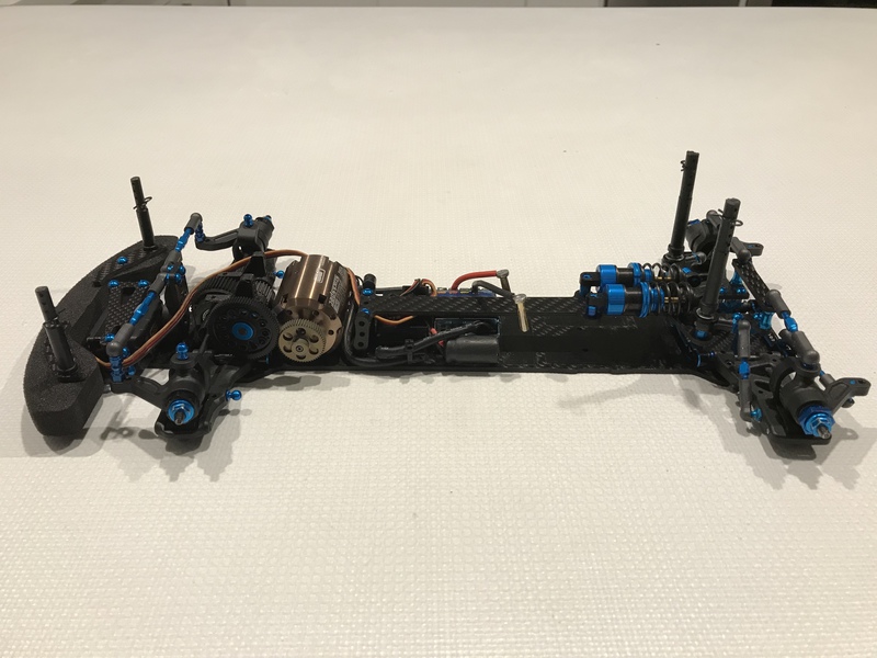
This week I will print a updated design. If it fits nice then Shapeways gotta do the final product.
I printed both bulkheads and installed them. Seating of the ballbearing could be better. They didn't went in without grinding. Even the screwholes needed a 2.5mm drill. Unfortunately I was to optimistic with the low position of the spur gear. I need to move it up 2mm to get clearance for the a-arm under load. Here now some first pictures:


This week I will print a updated design. If it fits nice then Shapeways gotta do the final product.
11-08-2017 | 09:23 AM
#24
Today I corrected all wrongs in the form and made several other changes to accomodate the print quality. Overall the bulkheads got beefier. I still hope that I can use them like they come to save the money for Shapeways 

 11-09-2017 | 01:47 AM
#27
Ackermann is controlled by a bunch of geometric parameters, including but not limited to the steering block mounting points, steering rack mounting points, and the steering rack design itself (sliding rack, single bellcrank, dual bellcrank etc).
11-09-2017 | 06:19 AM
#29
Tech Regular
Joined: Sep 2011
Posts: 491
From: Czech republic
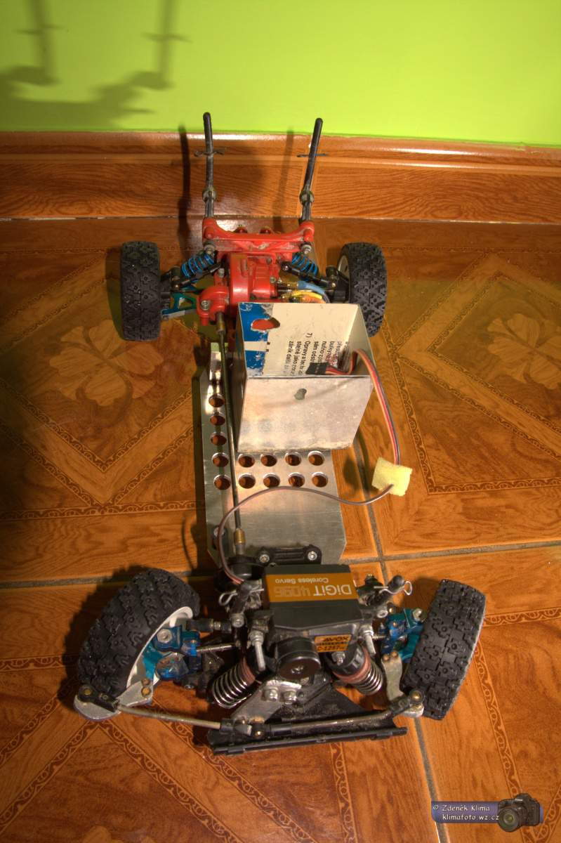
Edit: this is extreme version used in rally - it may inspire you
Last edited by Papi; 11-09-2017 at 06:38 AM.
