


 17Likes
RC Shock Dyno Test Results

 06-14-2015 | 08:32 PM
#77
Thread Starter
Tech Adept
Joined: Sep 2014
Posts: 100
I just got done with a busy couple of months that took me away from any significant dyno work. I did look into the impact testing more using the method I first tried, and I find my consistency and repeatability isn't where I need it to feel comfortable with publishing. I'm going to be working with a guy soon to design a fixture to improve that test. Once I get that designed, I should be able to publish the impact data people want to see. Thanks for the interest.
10-31-2015 | 10:51 PM
#78
Tech Master
Joined: Apr 2009
Posts: 1,056
From: South Africa
great stuff this OP, please consider posting up on the nitro offroad thread too, came across this googling for viscosity changes at temp and your work done on that alone with the AE oils makes this such an informative post..since most of the data people keep referring back to is so old im sure it is not even relevant anymore. thanks!!
12-09-2015 | 05:34 AM
#79
Tech Initiate
Joined: Aug 2009
Posts: 31
From: Paris France
Hello Scott,
Impressive works :-)
For your study about the piston hole size and the number of holes (page 25 of RC ShockdynoTest), my personal study points out also on the piston thickness.
Thin piston works as a diaphragm and thick piston gives more pressure loss through hole and more impact speed damping. In reality when your piston thickness is 2.5mm against a hole diameter of 1.2mm, that's not negligible and the piston thickness must be take in account for the study.
I also calculated theoretical reynolds number, for different pistons with multiple holes but the same flow area.
Increasing the number of holes while maintaining the same flow area (ie multiple of small holes VS two big holes) while give you turbulent mode (reynolds number >2000) at smaller speed, giving you more pack.
For exemple with the same flow area :
low speed damping (3 holes piston 1.1mm ; 1.1mm ; 1.2mm) = low speed damping (2 holes piston 1.4mm ; 1.4mm) (note that holes don't need to be all at the same diameter)
but
impact speed dampening(3 holes piston 1.1mm ; 1.1mm ; 1.2mm) > impact speed dampening(2 holes piston 1.4mm ; 1.4mm)
Hole diameter plays a role as it's use to calculate the hydraulic diameter for calculating the pressure loss
To sum up :
Impact speed depends on the thickness and the hole diameter
Low speed dampening depend on the flow aera (ie hole diameter and number of hole)
I made my theoretical study with Excel, and verify it in practice :-)
my two cent
Impressive works :-)
For your study about the piston hole size and the number of holes (page 25 of RC ShockdynoTest), my personal study points out also on the piston thickness.
Thin piston works as a diaphragm and thick piston gives more pressure loss through hole and more impact speed damping. In reality when your piston thickness is 2.5mm against a hole diameter of 1.2mm, that's not negligible and the piston thickness must be take in account for the study.
I also calculated theoretical reynolds number, for different pistons with multiple holes but the same flow area.
Increasing the number of holes while maintaining the same flow area (ie multiple of small holes VS two big holes) while give you turbulent mode (reynolds number >2000) at smaller speed, giving you more pack.
For exemple with the same flow area :
low speed damping (3 holes piston 1.1mm ; 1.1mm ; 1.2mm) = low speed damping (2 holes piston 1.4mm ; 1.4mm) (note that holes don't need to be all at the same diameter)
but
impact speed dampening(3 holes piston 1.1mm ; 1.1mm ; 1.2mm) > impact speed dampening(2 holes piston 1.4mm ; 1.4mm)

Hole diameter plays a role as it's use to calculate the hydraulic diameter for calculating the pressure loss
To sum up :
Impact speed depends on the thickness and the hole diameter
Low speed dampening depend on the flow aera (ie hole diameter and number of hole)
I made my theoretical study with Excel, and verify it in practice :-)
my two cent
12-09-2015 | 09:05 PM
#80
Thread Starter
Tech Adept
Joined: Sep 2014
Posts: 100
Thanks for the feedback and calculation efforts DarkRedemptor, they make sense. When I first did the multi-hole testing that had the tapered pistons, the results didn't completely make sense to me, but I think your explanation sounds right and fits those results too. So far, I have only done the low speed results, and feel fairly comfortable with those, but I am getting more convinced I will begin to see a different story once I do the pack testing. (soon, I promise!).
It seems most pistons, or at least different options for pistons made for a specific vehicle are the same thickness, so it isn't usually part of the tuning options. But a Tapered piston starts to change up the thickness variable. So I suspect this is where people would feel the difference... the amount of pack... and not in the "quicker rebound" as is typically marketed.
I'll see if I can do a thickness study too (just a simple one), but it will be a little more difficult for me to make a thinner piston than it is to drill out holes.
12-10-2015 | 11:28 PM
#81
Tech Initiate
Joined: Aug 2009
Posts: 31
From: Paris France
The piston thinness was a problem I have found on the Xray XB4 shock absorber, they are 2mm thin against 2.5mm for TRF (+20%) or 2.7mm for Kyosho. (+26%)
A way to test the thick influence is to use Xray piston inside Kyosho shock absorber with shim between the E-clip and the piston to remove backlash.
The other way (used to have better xb4 shock) is to counter bore the axle hole of a kyosho piston in order to put them in the xb4 shock
A way to test the thick influence is to use Xray piston inside Kyosho shock absorber with shim between the E-clip and the piston to remove backlash.
The other way (used to have better xb4 shock) is to counter bore the axle hole of a kyosho piston in order to put them in the xb4 shock
02-04-2016 | 11:44 PM
#82
Tech Addict
Joined: Jan 2004
Posts: 663
From: FearFarm - Arizona
The effects of heat and air expansion causing fade is interesting. I'll see if I can come up with a way to make a test that is repeatable to measure those effects. What do people believe are the most critical components to causing fade? Piston type? Oil? Bladder/type? (yes, I know heat is the issue, and that's caused by the shocks working hard and heating the oil over time) What do you racers typically do to prevent or minimize the fade? I can then test a worst case and a best case scenario and see how much different it is.
IMO there's a few factors that affect shock consistency/fade. We'll assume the shock is properly maintained with good seals, polished shafts etc and not talk about proper maintenance. There's plenty of discussion on that topic and IMO it's the number one factor for consistency. Now for shock fade or change in rebound....
I agree that heat increase is the biggest factor of shock consistency: As the shocks work, friction on the piston rubbing the shock body and the shock shaft rubbing the oring seals slowly build heat. Friction from the oil as it passes through the and around the pistons all generate heat. Longer runs mean more heat build up. This is less of an issue for short electric races.
Temp increase affects two things.
1. Oil viscosity thinner- hotter the oil the lower the viscosity
2. Internal Air Pressure increases as the temp increases in the shock. This adds rebound and 8th scale guys notice this most if they run a long race with emulsion shocks, less so if they run bladder with air above the bladder. and the none if they run vented foam. During the long races the ride height can change quite a bit just from the increases air pressure inside the shock body. (vent bladders have consistency issue for other reasons)
To test how much temp increase affects shock consistency, try a couple shock dyno experiment as follows:
____________
Exp #1 test consistency of shock oil damping as shock body temp increases.
1. Run 3 shocks with 3 different shock weights light, med, heavy oil. Use vented shock cap no foam to eliminate air pressure/foam as a factor (0 rebound)
leg #1 measure shock body temps of all shocks and record dyno results after 1 min.
leg #2 measure shock body temps of all shocks and record dyno results after 45mins.
With the resulting data plot shock damping before and after of the 3 shock oil weights. Plot rebound vs time of the 3 shock oil wieghts.
______________
Exp #2 test consistency of shock rebound(internal air pressure) as shock body temp increases.
1. Run 3 shock configs. Oil and pistons should be constant. Run 3 different rebound setups. 1) emulsion 25% rebound 2) standard sealed bladder 25% rebound 3) vented bladder with foam 25%rebound
leg #1 measure shock body temps of all the shocks and record dyno results after 1 min. remove shock and measure rebound distance and time to rebound.
leg #2 measure shock body temps of all the shocks and record dyno results after 45 mins. remove shock and measure rebound distance and time to rebound.
With the resulting data plot damping vs time and plot rebound distance vs time.
______________________
Most guys here can already predict the results, but it would be interesting to show the data to so we can all align on something on RC tech. hehe.
02-05-2016 | 12:13 AM
#83
Tech Addict
Joined: Jan 2004
Posts: 663
From: FearFarm - Arizona
Hello Scott,
Impressive works :-)
For your study about the piston hole size and the number of holes (page 25 of RC ShockdynoTest), my personal study points out also on the piston thickness.
Thin piston works as a diaphragm and thick piston gives more pressure loss through hole and more impact speed damping. In reality when your piston thickness is 2.5mm against a hole diameter of 1.2mm, that's not negligible and the piston thickness must be take in account for the study.
I also calculated theoretical reynolds number, for different pistons with multiple holes but the same flow area.
Increasing the number of holes while maintaining the same flow area (ie multiple of small holes VS two big holes) while give you turbulent mode (reynolds number >2000) at smaller speed, giving you more pack.
For exemple with the same flow area :
low speed damping (3 holes piston 1.1mm ; 1.1mm ; 1.2mm) = low speed damping (2 holes piston 1.4mm ; 1.4mm) (note that holes don't need to be all at the same diameter)
but
impact speed dampening(3 holes piston 1.1mm ; 1.1mm ; 1.2mm) > impact speed dampening(2 holes piston 1.4mm ; 1.4mm)
Hole diameter plays a role as it's use to calculate the hydraulic diameter for calculating the pressure loss
To sum up :
Impact speed depends on the thickness and the hole diameter
Low speed dampening depend on the flow aera (ie hole diameter and number of hole)
I made my theoretical study with Excel, and verify it in practice :-)
my two cent
Impressive works :-)
For your study about the piston hole size and the number of holes (page 25 of RC ShockdynoTest), my personal study points out also on the piston thickness.
Thin piston works as a diaphragm and thick piston gives more pressure loss through hole and more impact speed damping. In reality when your piston thickness is 2.5mm against a hole diameter of 1.2mm, that's not negligible and the piston thickness must be take in account for the study.
I also calculated theoretical reynolds number, for different pistons with multiple holes but the same flow area.
Increasing the number of holes while maintaining the same flow area (ie multiple of small holes VS two big holes) while give you turbulent mode (reynolds number >2000) at smaller speed, giving you more pack.
For exemple with the same flow area :
low speed damping (3 holes piston 1.1mm ; 1.1mm ; 1.2mm) = low speed damping (2 holes piston 1.4mm ; 1.4mm) (note that holes don't need to be all at the same diameter)
but
impact speed dampening(3 holes piston 1.1mm ; 1.1mm ; 1.2mm) > impact speed dampening(2 holes piston 1.4mm ; 1.4mm)
Hole diameter plays a role as it's use to calculate the hydraulic diameter for calculating the pressure loss
To sum up :
Impact speed depends on the thickness and the hole diameter
Low speed dampening depend on the flow aera (ie hole diameter and number of hole)
I made my theoretical study with Excel, and verify it in practice :-)
my two cent
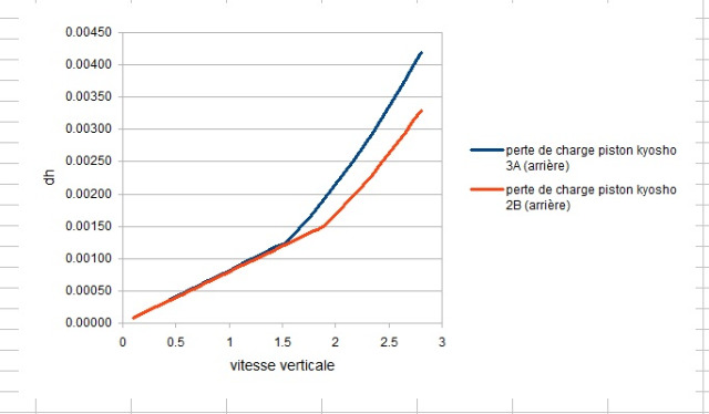
Based on the data, it shows smaller diameter holes with same velocity has more pack compared to less holes larger diameter. This data matches many people's personal experience, including my own.
The confusing part to me is... This is opposite what from the reynold's formula. Re=PVD/U
Where D is the diameter of the piston. If the piston diameter increases with no other changes the reynolds number (RE) should increase meaning it should pack quicker with larger piston holes.
Not sure what I'm missing here.
02-05-2016 | 08:23 PM
#84
Thread Starter
Tech Adept
Joined: Sep 2014
Posts: 100
The confusing part to me is... This is opposite what from the reynold's formula. Re=PVD/U
Where D is the diameter of the piston. If the piston diameter increases with no other changes the reynolds number (RE) should increase meaning it should pack quicker with larger piston holes.
Not sure what I'm missing here.
Where D is the diameter of the piston. If the piston diameter increases with no other changes the reynolds number (RE) should increase meaning it should pack quicker with larger piston holes.
Not sure what I'm missing here.
The key is thinking with the FLUID in mind. As you change the diameter of the hole, let's say to smaller holes, and assuming the same velocity of the piston in the shock, the same amount of fluid must pass through a smaller opening... making the fluid velocity FASTER, causing the Re number to increase when the diameter gets smaller.
If you like, I can post a picture of the formulas used to prove the above statement (I actually wrote it all down so I could convince myself I wasn't thinking crazy). But if you want to skip the steps in between, the final answer for the Reynolds number (assuming everything is constant except the hole diameter) is:
Re = (P*Vp*Dp^2)/(u*n*Dh)
Where P=density, Vp=Velocity of piston, Dp=Diameter of piston, u=viscosity, n=# of holes... And Dh is hole diameter.
With only the Hole diameter as a variable, it's in the denominator, so as it decreases, the Re number increases.
02-05-2016 | 08:44 PM
#85
Thread Starter
Tech Adept
Joined: Sep 2014
Posts: 100
I'm loving your results Icecyc1
Temp increase affects two things.
1. Oil viscosity thinner- hotter the oil the lower the viscosity
2. Internal Air Pressure increases as the temp increases in the shock. This adds rebound and 8th scale guys notice this most if they run a long race with emulsion shocks, less so if they run bladder with air above the bladder. and the none if they run vented foam. During the long races the ride height can change quite a bit just from the increases air pressure inside the shock body. (vent bladders have consistency issue for other reasons)
To test how much temp increase affects shock consistency, try a couple shock dyno experiment as follows:
____________
Exp #1 test consistency of shock oil damping as shock body temp increases.
______________
Exp #2 test consistency of shock rebound(internal air pressure) as shock body temp increases.
______________________
Most guys here can already predict the results, but it would be interesting to show the data to so we can all align on something on RC tech. hehe.
Those tests sound good, but honestly, I don't know that my dyno can handle 45min of continuous runtime, so I'd want to try to accelerate the test. If we are only looking at the heat factor changing the shock's damping and internal pressure, that is easy enough to accelerate with a heat gun or hair drier while running for only a few minutes. We know the piston moving in the oil generates heat through the friction of the fluid, and it can also emulsify the oil by pulling the air out of solution while running. So, if the key ingredient is heat, getting it warm while running it should at least show how much the damping and rebound should change after experiencing a higher temperature. What we won't get from an accelerated test is knowing how fast a piston/oil combination generates heat. And that I feel could be an extensive study.
I'll think about this a little more. It may be later this year. I'm deep into collecting Impact (pack) data now, and I hope to be able to report the results in the next few weeks once we figure out the best way to interpret and relate the data. (I've been reviewing the data with Bob Wright of RC Crew Chief, and Ray Munday Team Associated factory driver.)
02-05-2016 | 10:18 PM
#86
Tech Addict
Joined: Jan 2004
Posts: 663
From: FearFarm - Arizona
I'll admit, for a moment your interpretation of the formula confused me. But where you are in error is the interpretation of the variables. In short: P= density of the fluid, V= Velocity of the fluid, D= Diameter of the hole, U= viscosity.
The key is thinking with the FLUID in mind. As you change the diameter of the hole, let's say to smaller holes, and assuming the same velocity of the piston in the shock, the same amount of fluid must pass through a smaller opening... making the fluid velocity FASTER, causing the Re number to increase when the diameter gets smaller.
If you like, I can post a picture of the formulas used to prove the above statement (I actually wrote it all down so I could convince myself I wasn't thinking crazy). But if you want to skip the steps in between, the final answer for the Reynolds number (assuming everything is constant except the hole diameter) is:
Re = (P*Vp*Dp^2)/(u*n*Dh)
Where P=density, Vp=Velocity of piston, Dp=Diameter of piston, u=viscosity, n=# of holes... And Dh is hole diameter.
With only the Hole diameter as a variable, it's in the denominator, so as it decreases, the Re number increases.
This formula shows D (hole diameter) as the numerator.
The formula you shared has the D (hole diameter) as the denominator, so we would get opposite results depending on which formula is correct.
I did more digging and I see both examples so I'm not sure which is the right one to apply for our application.
02-05-2016 | 10:54 PM
#87
Thread Starter
Tech Adept
Joined: Sep 2014
Posts: 100
Ah this adds more confusion actually hehe. I think google led me to the wrong or different formula. http://ocw.mit.edu/courses/mechanica...bulentFlow.pdf
This formula shows D (hole diameter) as the numerator.
The formula you shared has the D (hole diameter) as the denominator, so we would get opposite results depending on which formula is correct.
I did more digging and I see both examples so I'm not sure which is the right one to apply for our application.
The key equation that is missing is the conservation of flow. Qp=n*Qh, where Q1 = Vp*Ap and Q2 = Vh*Ah. (Ah=pi/4*Dh^2) Since the Re formula needs the velocity of the oil through the hole (Vh), you must rearrange the flow formula for Vh. It ends up being:
Vh = (Vp*Ap)/(Ah*n).... and that is how the diameter of the hole ends up in the denominator. The Diameter of the piston is just used because you know the velocity of the shock and you are using that flow ratio to calculate the flow velocity through the hole.
I hope that's a little clearer???
02-05-2016 | 11:01 PM
#88
Tech Adept
Joined: Oct 2015
Posts: 165
That is because he is showing velocity as a function of the ratio of the hole diameters. The significant length in the Reynolds number is always on the top of the ratio, meaning as length increases, Re increases as do the influence of inertial vortex forces.
An important fundamental of Reynolds number is that it is a ratio of inertial vortex forces to viscous forces. Low numbers mean viscosity dominates and high numbers mean vorticity dominates....often referring to the tendency of a fluid to roll up into vorticies instead of staying smooth and laminar/viscous.
It takes a professor who really understands the subject to teach this appropriately in college/grad school so that the student gets a good handle on the fundamentals.
** looks like we were posting at the same time!
02-05-2016 | 11:22 PM
#89
Tech Regular
Joined: Feb 2015
Posts: 267
So does this mean that using more smaller holes gives a unique force/velocity curve that cannot be replicated with less holes by adjusting hole size and viscosity in the latter condition? Basically, is it worth trying different numbers of holes when tuning or is it a waste of time as you may as well just adjust hole size and viscosity?
02-06-2016 | 10:06 AM
#90
One thing that needs to be considered besides just the Re No is the orifice discharge coefficient (Cd). For short tube orifices, which we have, the discharge coefficient varies with Re No. and the L/Dh ratio (piston thickness/orifice diameter). The graph below shows the Force vs Piston Velocity (F-V) characteristics for two pistons with the same total orifice area. One has 6 holes and one has 3. As you can see the piston with more smaller holes produces much higher force than the piston with fewer larger holes. This is a result of the Cd coefficient.
Note that this damper model does not account for fluid compressibility. What compressibility will do is significantly reduce the force the damper produces during the first half of the compression stroke. This effect will be much much more pronounced at higher velocities. Pack velocities as they are referred to.
This model is being validated along with Icecyc1's work so I am very confident the effect of hole size is real. We see this effect in the dyno results.