


 16Likes
The Homebuilt Dynamometer (Dyno)Thread!!!
 04-10-2024 | 01:03 PM
#106

Digging up and old thread here since it seems like a better place to post the stuff I have been working on. I have also been using the Simple Dyno software even though the developer no longer supports it. I use an Arduino to record the RPM, voltage and current data. I have been working on an improved way to record the data but I need to get an Arduino with more RAM (currently using an Arduino Nano). I plan to record the time for each revolution of the flywheel. I have done this with the Nano but run out of space after 1 second or so. My flywheel design usually results in 5 or 6 second runs. I will post some pics and data when I get home.
Out of curiosity, how are you running out of space?
 04-10-2024 | 02:08 PM
#107
This isn't a problem when using the provided sketch from the Simple Dyno software but that setup works a little bit differently. It takes data at fixed intervals and measures the next rotation of the flywheel. The problem being that I am trying to take data from 0 rpm and if the interval is too fast, you will get 2 of the same data point. To counter this, I have set the data taking interval to 20msec which is borderline in terms of resolution.
 04-10-2024 | 02:46 PM
#109
One version of my code dumps all the data into an array and then at the end of the run, streams it to the serial port. This setup measures the rotational time for every rotation of the flywheel and has to record RPM, Voltage and Current for each data point. This differs from how most setups work where the data is streamed live to the serial port. I found that the serial can not be used without causing missed interrupts for the RPM measurement. My plan is to try an Arduino Minima board which has 16x the memory.
This isn't a problem when using the provided sketch from the Simple Dyno software but that setup works a little bit differently. It takes data at fixed intervals and measures the next rotation of the flywheel. The problem being that I am trying to take data from 0 rpm and if the interval is too fast, you will get 2 of the same data point. To counter this, I have set the data taking interval to 20msec which is borderline in terms of resolution.
This isn't a problem when using the provided sketch from the Simple Dyno software but that setup works a little bit differently. It takes data at fixed intervals and measures the next rotation of the flywheel. The problem being that I am trying to take data from 0 rpm and if the interval is too fast, you will get 2 of the same data point. To counter this, I have set the data taking interval to 20msec which is borderline in terms of resolution.
What are you using for the inertial load? Eventually I was going to go back and work on a dyno again, but the things that stop me are the inertial load and the front end software.
04-10-2024 | 02:53 PM
#110
For a quick build I did, I used the sensor cable and measured the time between rising edges of the hall sensors. I used input polling for this instead of interrupts. This allowed 3 measurements per rotation. It was a bit erratic after about 10k RPM, but I never went back and revisited it. I like some of the things with the R4, but the Reneses MCU isn't the most user friendly. I was considering going to an STM32. Of course I have an Arduino Giga R1 that is not being used...
What are you using for the inertial load? Eventually I was going to go back and work on a dyno again, but the things that stop me are the inertial load and the front end software.
What are you using for the inertial load? Eventually I was going to go back and work on a dyno again, but the things that stop me are the inertial load and the front end software.
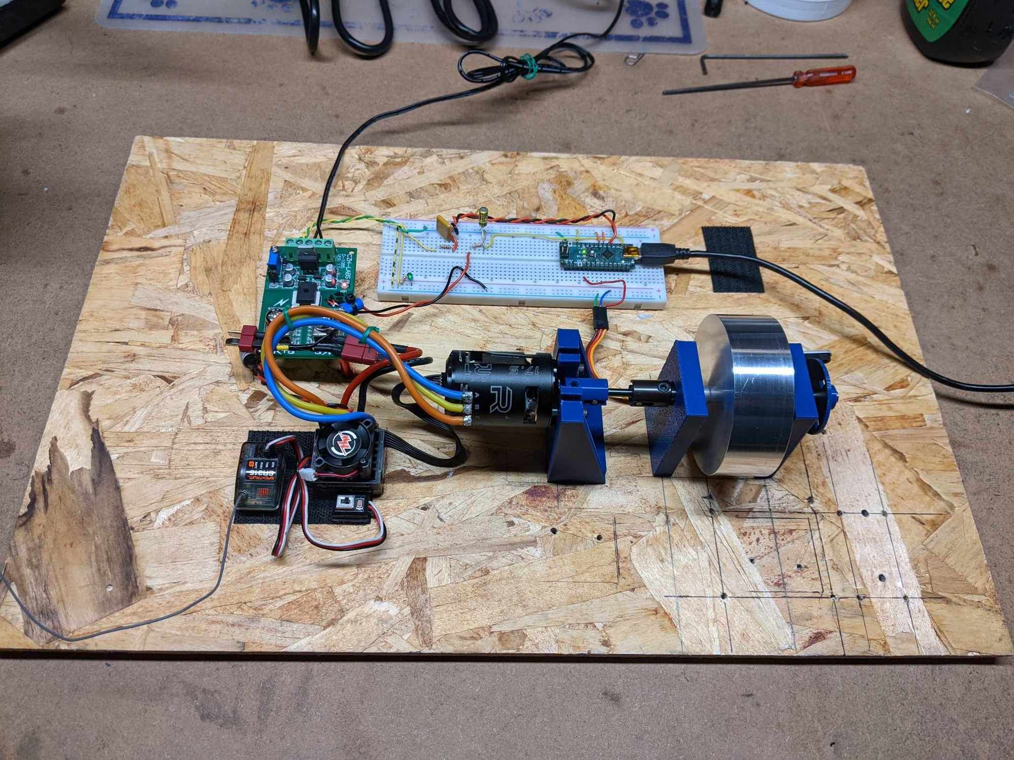
The flywheel load is homemade from a piece of 6061 aluminum. It is 3" diameter, 1 inch thick and weighs 324g. The MOI is around 0.0002334 kg-m^2.
04-10-2024 | 03:34 PM
#111
My very first test did the same thing with the sensors in the BL motor. I decided to do an external measurement instead because I wanted brushed motor capability. I also did the input polling but wasn't satisfied with the higher rpm performance. I found that dumping the data to an memory array works well but you do need enough memory to hold the whole run.
The flywheel load is homemade from a piece of 6061 aluminum. It is 3" diameter, 1 inch thick and weighs 324g. The MOI is around 0.0002334 kg-m^2.
The flywheel load is homemade from a piece of 6061 aluminum. It is 3" diameter, 1 inch thick and weighs 324g. The MOI is around 0.0002334 kg-m^2.
04-10-2024 | 04:54 PM
#112
Tech Initiate
iTrader: (1)
Joined: Sep 2020
Posts: 35
I built my dyno using information from Bob Wright and use his software (RC Crew Chief) to process it. Unfortunately Bob is no longer with us.
The dyno uses an arduino uni that is read using Bob's software. RPMs are read using a disc with 16 holes in it using an opto.
I also built a driver to drive the esc so I don't need to use my radio to do the tests.
The dyno uses an arduino uni that is read using Bob's software. RPMs are read using a disc with 16 holes in it using an opto.
I also built a driver to drive the esc so I don't need to use my radio to do the tests.
04-10-2024 | 04:59 PM
#113
04-10-2024 | 05:00 PM
#114
I built my dyno using information from Bob Wright and use his software (RC Crew Chief) to process it. Unfortunately Bob is no longer with us.
The dyno uses an arduino uni that is read using Bob's software. RPMs are read using a disc with 16 holes in it using an opto.
I also built a driver to drive the esc so I don't need to use my radio to do the tests.
The dyno uses an arduino uni that is read using Bob's software. RPMs are read using a disc with 16 holes in it using an opto.
I also built a driver to drive the esc so I don't need to use my radio to do the tests.
04-10-2024 | 05:08 PM
#115
Can you tell if his software is measuring number of ticks in a given period of time or time between ticks?
Uses interrupts to measure the time between pulses from an optical sensor and an encoder wheel.
Same measuring method as the MiniPro
04-10-2024 | 05:43 PM
#118
04-10-2024 | 05:48 PM
#119
Actually I made the assumption that the MiniPro measures time between ticks, as I think the other way is prone to error... Just because the sample rate says 10Hz, doesn't mean it is counting the ticks for 100ms. Just could be the reading at 100ms. My setup was obviously measuring time between ticks, and I was spitting out the reading every 100ms.
