


 231Likes
RCHourglass DIY Lap Timing (AKA Cano revised)
 01-14-2022 | 06:01 AM
#766
Thread Starter
Tech Regular
Joined: Mar 2015
Posts: 358
The piezo is configurable from RCHourglass manager, or via serial port commad SET BEEP [0-255] [0 or 6-30] Set beep notification in ms when passage is detected. Duration 0 = no beep notification. Divider sets beeper frequency: 0 is only pulse, otherwise frequency is 20kHz/divider, where divider must be between 6 and 30.
 01-15-2022 | 05:51 AM
#767
Tech Apprentice
Joined: Jan 2013
Posts: 61
From: Schoonebeek
The piezo is configurable from RCHourglass manager, or via serial port commad SET BEEP [0-255] [0 or 6-30] Set beep notification in ms when passage is detected. Duration 0 = no beep notification. Divider sets beeper frequency: 0 is only pulse, otherwise frequency is 20kHz/divider, where divider must be between 6 and 30.
I have here a Piezo_buzzer with built in driver which can work from 5V DC without the need to select the correct frequency: BeStar BPT2412XH16LF
It doesn't write clearly in the specifications, but I just tried, it works direct from DC, no need to control the frequency.
01-15-2022 | 10:40 AM
#768
Tech Apprentice
Joined: Jan 2013
Posts: 61
From: Schoonebeek

Please advice:
I bought some PSoC kits this week. Installed the adviced Programmer from the Cypress site and tried to upload the latest .hex file.
All fine, no errors.
I attached a 5MHz crystal as well as the two 22pF's like in several diagrams is shown to 15.2 and 15.3
But when I connect the small USB connector to a 2nd USB port, the device manager doesn't show another COM-port.
I did NOT supply the PSoC by 5V at pin VDDIO, because I measured 4.8V DC at that pin already (=due to PC USB also being connected to the large USB pads).
I measured the 15.2 and 15.3 pin of the PSoC, but there is no oscillation found. Changed the crystal out for another one did not solve it.
What is going on here?? In Marco's post that shows the method, the programming takes 23 seconds, in my case just below 4.
It looks like the target is not programmed....is my setting in the Programming environment wrong somewhere?
My PSoC setup is at this moment thus as minimal as possible, only connected the 5Mhz crystal + cap's. Supply of the PSoC through the daughterboard.
Then I tried if I could program at all. so I did the project described here which indeed worked and my blue LED can blink:
01-15-2022 | 12:07 PM
#770
Tech Apprentice
Joined: Jan 2013
Posts: 61
From: Schoonebeek
I was put the wrong direction because in some early post from other builders were pictures shown were the crystal was at the 15.2 and 15.3....See here below....
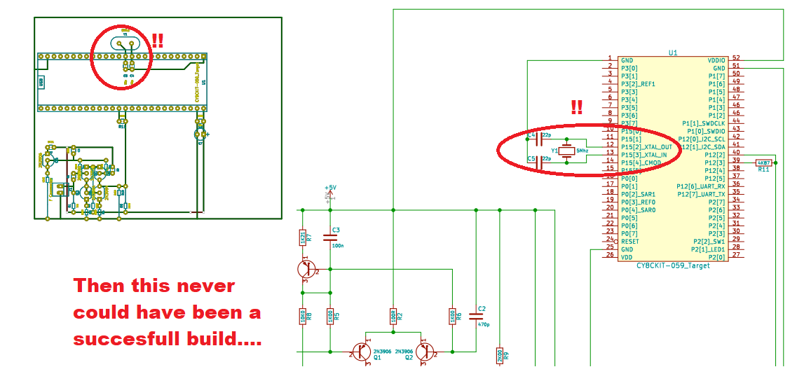
And also because the writing on the PSoC PCBA itself indicates the other 2.
I try now and let you know later this evening.
 01-16-2022 | 02:22 AM
#773
Tech Apprentice
Joined: Jan 2013
Posts: 61
From: Schoonebeek

Yes! Also managed to take this hurdle....So I had to include the <CR><LF> in the TX command ;-) ....
@Marco (mv4wd) You can find my €30 donation to charity in you email inbox.
Decoder is now found under COM10 in my case.
-> Update: ZRound detected the decoder in CANO Mode....not using port: 10, but port: COM10....it's in the small details :-).
Last edited by PA3EXV; 01-16-2022 at 03:07 AM.
01-16-2022 | 04:48 AM
#774
Tech Apprentice
Joined: Jan 2013
Posts: 61
From: Schoonebeek

8 years of development (Howard -> Marco) captured in one picture. Goal of today is to cut my old decoder hardware in two, re-use the Coax-input and connect the new design to see if we can detect a transponder.
01-16-2022 | 05:55 AM
#775
Thread Starter
Tech Regular
Joined: Mar 2015
Posts: 358
Please don't cut that piece of history  Better to make a new front end or better add a jumper to the old one and put both circuits in the box, so you can even compare the two design performance. I think it's something never done before
Better to make a new front end or better add a jumper to the old one and put both circuits in the box, so you can even compare the two design performance. I think it's something never done beforeLast edited by mv4wd; 01-16-2022 at 05:55 AM. Reason: typo
01-16-2022 | 12:30 PM
#776
Tech Apprentice
Joined: Jan 2013
Posts: 61
From: Schoonebeek
@Marco: By using Monitor mode, I receive these packets. From years ago when I made my transponder according the old Cano design, I programmed '404040' as the ID. Can you agree I should set the 6 digits in Zround for the tansponder_number, or should there be 8? What to do??
I hoped I could read the real ID from your RC Hourglass Manager, by learning a transponder. but that didn't help me. There only RC4 transponders can be learned.
Last edited by PA3EXV; 01-16-2022 at 01:02 PM.
01-16-2022 | 02:02 PM
#777
Thread Starter
Tech Regular
Joined: Mar 2015
Posts: 358
Monitor Mode spits out the packets as received, no decoding takes place. If you want to have the 'Cano' style decoding (that is no decoding) you must use the command CANO CLASSIC MODE . But in this way RC3 transponders will not be detected with the number stamped on the case. I suggest you re-encode your transponders with the RCHourglass Manager function for PIC programming. Please have a look at command reference on the project wiki
01-16-2022 | 02:57 PM
#778
Tech Apprentice
Joined: Jan 2013
Posts: 61
From: Schoonebeek
Monitor Mode spits out the packets as received, no decoding takes place. If you want to have the 'Cano' style decoding (that is no decoding) you must use the command CANO CLASSIC MODE . But in this way RC3 transponders will not be detected with the number stamped on the case. I suggest you re-encode your transponders with the RCHourglass Manager function for PIC programming. Please have a look at command reference on the project wiki
Thank you again for your quick response and have a good week.
Gerrie
01-18-2022 | 04:41 AM
#779
Tech Apprentice
Joined: Jan 2013
Posts: 61
From: Schoonebeek
These stupid component shortage globally...not only affecting my daily job, but now also the evening hobby....Just finished my SMT version with the PIC16F18313, did a quick check on availability before ordering the PCBA....Now need to change all to the DIP version PIC. Oh well, then I don't need the ISP pins anymore and can use the RC Hourglass programming socket. That saves some space on the PCBA ;-))
01-18-2022 | 06:54 AM
#780
Tech Apprentice
Joined: Jan 2013
Posts: 61
From: Schoonebeek
OK, few hours later the DIP8 versions done. The idea is to use the round shape if the PCBA is to be mounted inside a PVC ring, cut of 32mm PVC, some 8.5mm height. The outer surface of the ring can have a groove machined in, in which the windings will fit. In case a dedicated 3Dprinted housing can be made, the disc PCBA is cut into a square which remains as a 18mm x 18mm transponder PCBA. In that case the windings are in 'free-air' fixated by the 4 poles that I see others do before me.
Last edited by PA3EXV; 01-23-2022 at 03:09 AM.