


 8Likes
Lap Timing Decoder


 09-09-2013 | 12:25 AM
#287
Tech Apprentice
Joined: Jan 2013
Posts: 61
From: Schoonebeek
This weekend I finished my proto for the transponder, loop_amplifier and the first part of the decoder hardware. I succeeded in programming the 12F683 with code that generates the preamble and a ID, for now in a fixed delay_loop of 2mS - 4mS to give me a better way of analysing the loop_amplifier and decoder. Later I will do the random 2mS - 4mS delay.
My question: What is the expected amplitude at the Phase_Detector_Input_Amplifier when the transponder is placed in the middle of a 10'x 1' loop, assuming the transponder coil is resonant at 5MHz? I have too much noise at the output of the 74HC04. I think there is something wrong in my loop_amplifier. Anyone to feedback to me what the signal_amplitude should be with a 1:10 scope probe? Thank you.
My question: What is the expected amplitude at the Phase_Detector_Input_Amplifier when the transponder is placed in the middle of a 10'x 1' loop, assuming the transponder coil is resonant at 5MHz? I have too much noise at the output of the 74HC04. I think there is something wrong in my loop_amplifier. Anyone to feedback to me what the signal_amplitude should be with a 1:10 scope probe? Thank you.
09-11-2013 | 08:19 AM
#288
This weekend I finished my proto for the transponder, loop_amplifier and the first part of the decoder hardware. I succeeded in programming the 12F683 with code that generates the preamble and a ID, for now in a fixed delay_loop of 2mS - 4mS to give me a better way of analysing the loop_amplifier and decoder. Later I will do the random 2mS - 4mS delay.
My question: What is the expected amplitude at the Phase_Detector_Input_Amplifier when the transponder is placed in the middle of a 10'x 1' loop, assuming the transponder coil is resonant at 5MHz? I have too much noise at the output of the 74HC04. I think there is something wrong in my loop_amplifier. Anyone to feedback to me what the signal_amplitude should be with a 1:10 scope probe? Thank you.
My question: What is the expected amplitude at the Phase_Detector_Input_Amplifier when the transponder is placed in the middle of a 10'x 1' loop, assuming the transponder coil is resonant at 5MHz? I have too much noise at the output of the 74HC04. I think there is something wrong in my loop_amplifier. Anyone to feedback to me what the signal_amplitude should be with a 1:10 scope probe? Thank you.
09-19-2013 | 04:55 AM
#289
Tech Rookie
Joined: Sep 2013
Posts: 2
Hi Howard! Congratulations on an excellent project!! I really enjoyd reading you posts.
I also started with the same project 1,5 years ago, but never finished it. Now I found your thread and see that you have solved it, great job!
I would love to help you with anything that needs to be addressed. I'm a software/hardware engineer with special focus on embedded software and .NET software. Please let me know how I can contribute to this awesome project.
Regards Geir.
09-19-2013 | 06:45 AM
#290
Hi Howard! Congratulations on an excellent project!! I really enjoyd reading you posts.
I also started with the same project 1,5 years ago, but never finished it. Now I found your thread and see that you have solved it, great job!
I would love to help you with anything that needs to be addressed. I'm a software/hardware engineer with special focus on embedded software and .NET software. Please let me know how I can contribute to this awesome project.
Regards Geir.
I also started with the same project 1,5 years ago, but never finished it. Now I found your thread and see that you have solved it, great job!
I would love to help you with anything that needs to be addressed. I'm a software/hardware engineer with special focus on embedded software and .NET software. Please let me know how I can contribute to this awesome project.
Regards Geir.
We've mentioned before that all of the digital circuitry (not including the microprocessor) would fit into a small, inexpensive FPGA, so maybe you'd like to do that? If so, I can send you what I've done so far with the Altera EPM3064.
09-20-2013 | 01:22 PM
#292
Tech Apprentice
Joined: Jan 2013
Posts: 61
From: Schoonebeek
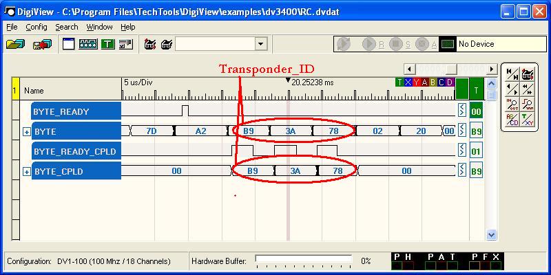
This post must make Howard proud once more; After a few others already succeeded in getting a system up and running, I can now as well give you all the good news! Today we managed to get the 'valid' signal as well as the three succeeding nByte_ready pulses to read the 3 ID_Bytes into the decoder processor. The processor is not added to our board yet, that will be the next step. Having the signals available from my transponder (PIC12F683 based as original in the Howard-design), this is a very satisfying stage in the project. It means the transponder software I did is indeed doing the correct preamble and as well transmits the ID that is desired. In the below pictures I would like to share some views on the hardware I build.
Because a collegue at work is very kind and interrested in what I am doing as RC-hobby and electronics, he was so kind to tranfer the breadboard containing over 20 TTL chips into a CPLD. We have used the 40MHz from the breadboard next to the serial_data received from the loop_amplifier (74AC04 output) to create the same 'Byte_ready' and the 8 bit word that will go into the decoder_processor. This is presented in the pictures that are taken from the logic-analyser we have used to debug. For your information, the CPLD code is 57 flip_flops and fits into the Altera EPM3064. However we did not have that device on hand and used a Altera MAX II.
Here are the pictures:
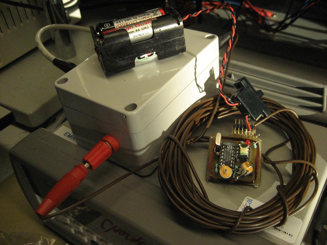
I started few weeks ago on the transponder, loop_amplifier and prgrammed the PIC:
The breadboard which I finished next:
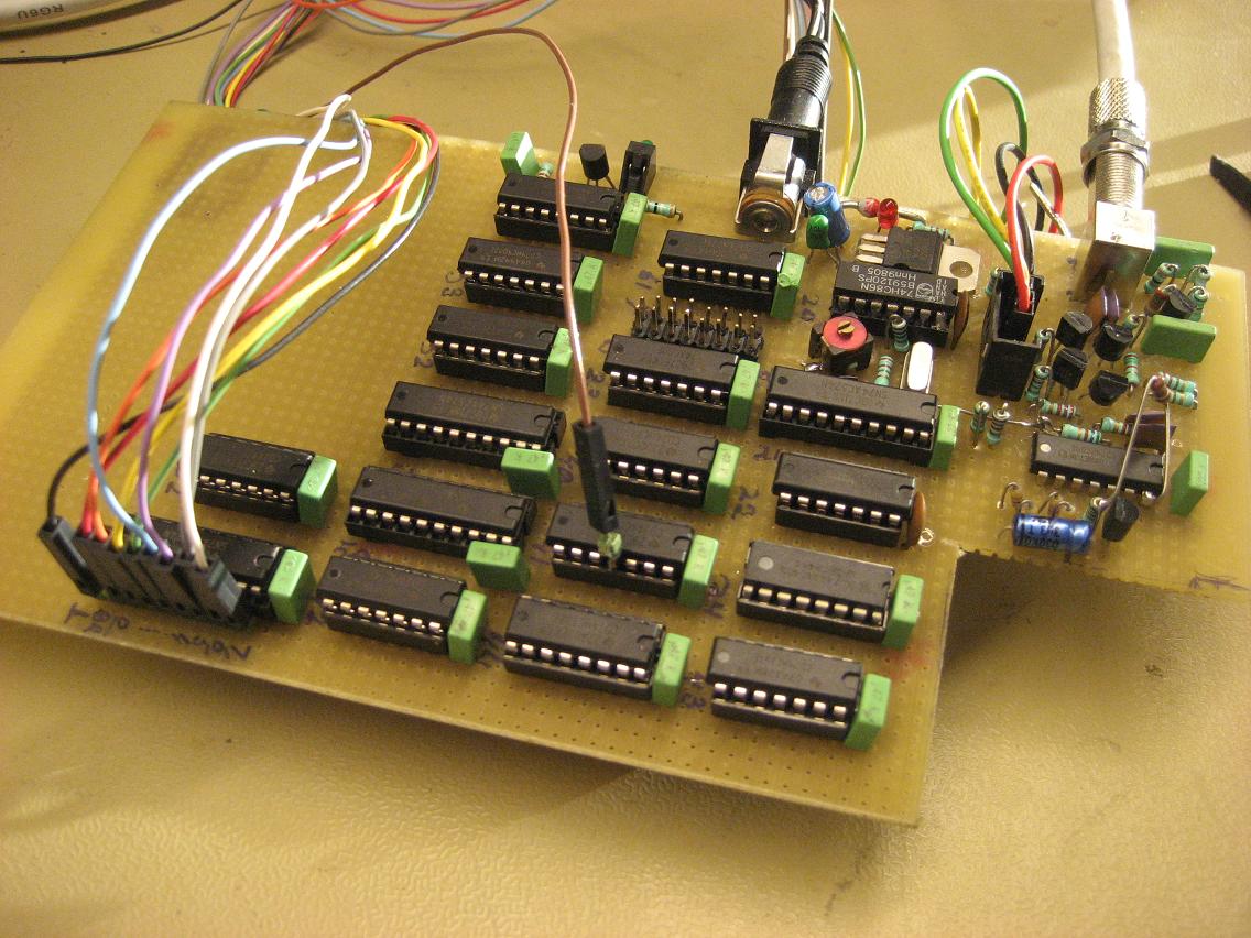
A different view on the breadboard:
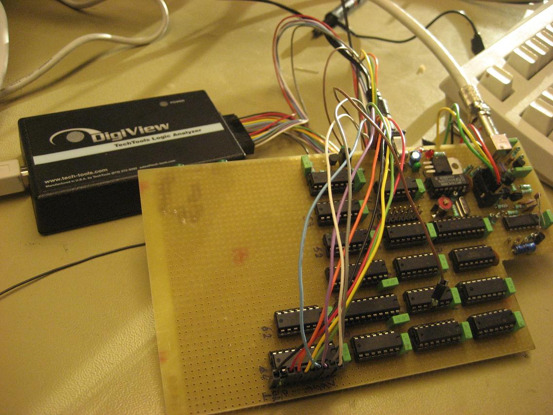
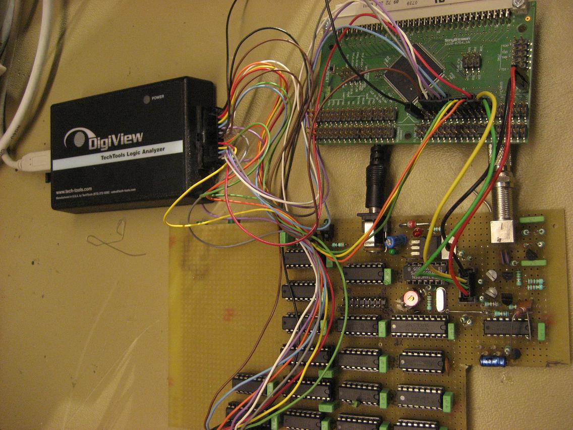
Here the breadboard next to the CPLD board during debuging:
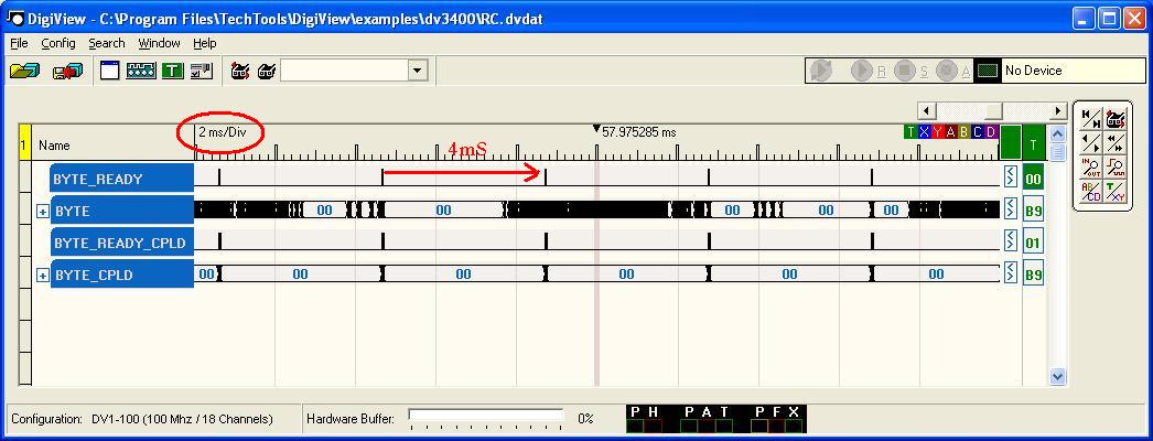
And finally two pictures taken from the logic_analyser in which the 4mS test interval of the transponder ID message is shown (Howards' ID for test purpose used)
Next thing to start working is the implementation of the random delay of 2 - 4mS in between of the transponder messages. I already found a way to acomplish this in ASM, I haven't had time yet to test it in the 12F683 PIC of the transponder. Next to this we will start on the decoder_processor. Howard already gave us some great ideas for this and from that we can write the specific message that I would like to get from the decoder to feed into the lap_counter software of my own choice (RF_Lapcounter). I have in the past already did some research what exactly is needed to use this software (post # 78). I realy like that software without digging into the ZRound and others. I found the function to couple your own picture of the car and the picture of the driver nicely done. Because we an in control ourselves, we can send out whatever message we need for our solution. That's the nice think of this open source project.
So far I enjoyed contructing and programming very much. In my daily work I never got into PIC-programming so far (despite being occupied into electronics already for over 25 years). I found this project a great drive to start with that, something I would not have started on because there was no big reason to do so. Without a good goal, someone would not start programming assembly or even learn dealing with microcontrollers.
Big thanks to Howard for the inspiration, I hope it will also help others to take that the step to start designing. Nowadays not much young people can be inspired to get away from the PC playing games. We need them in the industry!
Gerrie, PA3EXV
Because a collegue at work is very kind and interrested in what I am doing as RC-hobby and electronics, he was so kind to tranfer the breadboard containing over 20 TTL chips into a CPLD. We have used the 40MHz from the breadboard next to the serial_data received from the loop_amplifier (74AC04 output) to create the same 'Byte_ready' and the 8 bit word that will go into the decoder_processor. This is presented in the pictures that are taken from the logic-analyser we have used to debug. For your information, the CPLD code is 57 flip_flops and fits into the Altera EPM3064. However we did not have that device on hand and used a Altera MAX II.
Here are the pictures:
I started few weeks ago on the transponder, loop_amplifier and prgrammed the PIC:
The breadboard which I finished next:
A different view on the breadboard:
Here the breadboard next to the CPLD board during debuging:
And finally two pictures taken from the logic_analyser in which the 4mS test interval of the transponder ID message is shown (Howards' ID for test purpose used)
Next thing to start working is the implementation of the random delay of 2 - 4mS in between of the transponder messages. I already found a way to acomplish this in ASM, I haven't had time yet to test it in the 12F683 PIC of the transponder. Next to this we will start on the decoder_processor. Howard already gave us some great ideas for this and from that we can write the specific message that I would like to get from the decoder to feed into the lap_counter software of my own choice (RF_Lapcounter). I have in the past already did some research what exactly is needed to use this software (post # 78). I realy like that software without digging into the ZRound and others. I found the function to couple your own picture of the car and the picture of the driver nicely done. Because we an in control ourselves, we can send out whatever message we need for our solution. That's the nice think of this open source project.
So far I enjoyed contructing and programming very much. In my daily work I never got into PIC-programming so far (despite being occupied into electronics already for over 25 years). I found this project a great drive to start with that, something I would not have started on because there was no big reason to do so. Without a good goal, someone would not start programming assembly or even learn dealing with microcontrollers.
Big thanks to Howard for the inspiration, I hope it will also help others to take that the step to start designing. Nowadays not much young people can be inspired to get away from the PC playing games. We need them in the industry!
Gerrie, PA3EXV
Last edited by PA3EXV; 09-20-2013 at 01:47 PM.
09-20-2013 | 04:13 PM
#293
Thanks for reading the thread, Mo! It may not be particularly interesting for those people who are not well-versed in electronics, but it does give some idea of how these things are created.
09-20-2013 | 04:27 PM
#294
So far I enjoyed contructing and programming very much. In my daily work I never got into PIC-programming so far (despite being occupied into electronics already for over 25 years). I found this project a great drive to start with that, something I would not have started on because there was no big reason to do so. Without a good goal, someone would not start programming assembly or even learn dealing with microcontrollers.
09-30-2013 | 01:14 AM
#296
Tech Apprentice
Joined: Aug 2013
Posts: 52
Hello guys!
I'm using decoder from Payalneg.
There is little problem - he is very busy now, and I need advice.
Decoder and loop work awesome, but we have 1 problem - if our loop length is greater than 10m - we have misses.
May be you can get me advice - what cable may I try as loop? What Awg I need?
Maybe can try to do new loop amplifier?
And another - what about coaxial cable? Is AMB cable will be best solution?
We need cable about 20 m length.
Or maybe we can get full loop from amb?
09-30-2013 | 02:53 AM
#297
Hello guys!
I'm using decoder from Payalneg.
There is little problem - he is very busy now, and I need advice.
Decoder and loop work awesome, but we have 1 problem - if our loop length is greater than 10m - we have misses.
May be you can get me advice - what cable may I try as loop? What Awg I need?
Maybe can try to do new loop amplifier?
And another - what about coaxial cable? Is AMB cable will be best solution?
We need cable about 20 m length.
Or maybe we can get full loop from amb?
I'm using decoder from Payalneg.
There is little problem - he is very busy now, and I need advice.
Decoder and loop work awesome, but we have 1 problem - if our loop length is greater than 10m - we have misses.
May be you can get me advice - what cable may I try as loop? What Awg I need?
Maybe can try to do new loop amplifier?
And another - what about coaxial cable? Is AMB cable will be best solution?
We need cable about 20 m length.
Or maybe we can get full loop from amb?
http://www.rctech.net/forum/12222187-post251.html
The coaxial cable should be 75 ohm. As long as the cable quality is good, it doesn't matter where you purchase it. I have updated post #251 with this information.
09-30-2013 | 02:59 AM
#298
Tech Apprentice
Joined: Aug 2013
Posts: 52
10m is far too long. The acceptable sizes and construction specs for the loop are here:
http://www.rctech.net/forum/12222187-post251.html
The coaxial cable should be 75 ohm. As long as the cable quality is good, it doesn't matter where you purchase it. I have updated post #251 with this information.
http://www.rctech.net/forum/12222187-post251.html
The coaxial cable should be 75 ohm. As long as the cable quality is good, it doesn't matter where you purchase it. I have updated post #251 with this information.
Can you explain please - specs for loop says that I need you jumper in amplifier. I have Payalneg's amplifier - it is same?
10 meter it is all length of loop. Our track is 5 meter width. And here it works fine.
The problems we have only at 6.5 meter width track.
Last edited by maeg; 09-30-2013 at 03:28 AM.
09-30-2013 | 05:45 AM
#299
Thank you, Howard.
Can you explain please - specs for loop says that I need you jumper in amplifier. I have Payalneg's amplifier - it is same?
10 meter it is all length of loop. Our track is 5 meter width. And here it works fine.
The problems we have only at 6.5 meter width track.
Can you explain please - specs for loop says that I need you jumper in amplifier. I have Payalneg's amplifier - it is same?
10 meter it is all length of loop. Our track is 5 meter width. And here it works fine.
The problems we have only at 6.5 meter width track.
A 12' x 1' loop might work fine with a 5m (15') track width, as long as it is centered on the track. This is because the loop also picks up transponder signals that are slightly outside of the enclosed area.
My answers only apply to my design. You can try to send Payalneg a private message regarding his design.
It would also be worthwhile to build one of my loop amplifiers and see if that helps.
09-30-2013 | 05:57 AM
#300
Tech Apprentice
Joined: Aug 2013
Posts: 52
My apologies, I thought you meant the loop was 10m wide. Now I think you meant circumference.
A 12' x 1' loop might work fine with a 5m (15') track width, as long as it is centered on the track. This is because the loop also picks up transponder signals that are slightly outside of the enclosed area.
My answers only apply to my design. You can try to send Payalneg a private message regarding his design.
It would also be worthwhile to build one of my loop amplifiers and see if that helps.
But then first question - may be it need to do some changes so you loop amplifier can work on our wide outdoor track - 6.5 meters?