Originally Posted by
the incubus
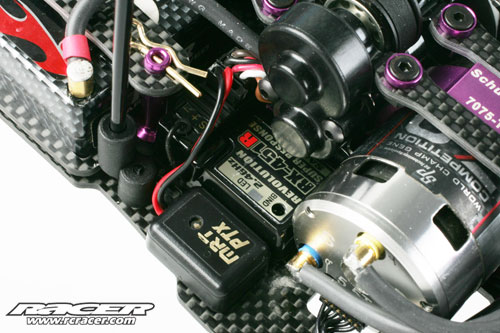
Not one bit. They really did a bang up job with their stuff this time around. Referencing the images below, the motor leads stick out about 3/16" and that's it. They also slide in rather firmly and don't slide out very easily which is a major plus.
You solder your motor leads right onto the female bullet receiver connectors and the motor itself has the Bullets they slide into. I'll try and snap a pic of mine for you, though I was certain I had but I can't find them ATM.


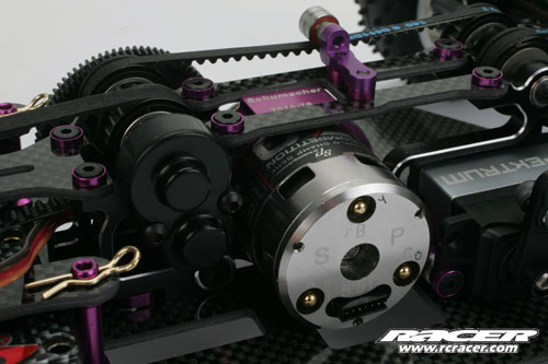
This picture shows how neat and tidy the end bell is:
I just wish they could revise it so all the connections reside right next to one another.
Here it is with leads all soldered up:
Ok so the stock photo shows the motor with the bullets inserted. I was worried you connected something additional to what was hanging out the back just showing in that photo.
I assume the motor comes with a set of the bullets...right?
Originally Posted by
Cain
I have this motor. the connectors don't stick out far at all. Its kind of nice to just unplug and change.
The motor is smooth for sure, if you need torque though you will want the 12.5mm rotor they sell, one of which is like getting unobtanium at times ... I had to hunt it down myself.
The sensor boards ... I would suggest if you have an ESC that can do timing, SIMULATE the timing on the motor using it to get an idea what kind of board you would want. The Green Board and Yellow Boards are pretty common though.
Well my ESC can do timing but this is for 17.5 blinky so per rules that is a no no...as I assume changing rotors and sensor boards would be. Is that assumption correct?