


RCbenchmark Dynamometer motor tester
 11-08-2015 | 03:57 PM
#1
Thread Starter
Tech Addict
Joined: Sep 2014
Posts: 509
From: London, United Kingdom
The RCbenchmark dynamometer is the first tool that enables designers to fully characterize brushless motors and propellers. You can control the motor and measure all the key variables with high accuracy. Our tool records voltage, current, torque, thrust, and rotation speed. Test motor integrity with a built-in precision winding ohmmeter. With the ability to also act as a weight scale, this tool will reduce the development time and the performance of your next design.
 11-08-2015 | 05:23 PM
#2
Tech Initiate
Joined: Nov 2015
Posts: 22
From: Gatineau, QC, Canada
Hi. I designed the RCbenchmark dynamometer. I will be available here to answer your questions on our product, DIY solutions, and motor testing in general. I will do my best to answer your questions, and your feedback will be helpful to improve our tutorials, software (which is open source btw) and products.
11-09-2015 | 04:41 AM
#3

Many thanks to Mr. Phaneuf for creating this thread while I was out racing!
Welcome to RCTech, Jebarus! And thank you for offering your dynamometer to the public.
All of my comments below apply to RC car motors:
Of utmost importance is determining the peak power output for a motor. It is also very useful to get a complete (or as nearly complete as possible) curve of output power vs RPM, over the full range of RPM. Efficiency is of lesser interest, but is still useful information.
The dyno results would be used for comparing different motors, and also to determine the commutation timing setting that gives maximum output. In many racing classes, rules require that the timing remain fixed while the motor is in use. In other classes, the timing may be electronically varied (this is called "dynamic timing", "ramping", "boost", etc.), so the dyno can be used to find the timing that gives maximum power output at any given RPM, with the final goal being to create the optimum timing advance curve to program into the ESC.
A flywheel dyno is best for our application because it can give all of the information (at least for one motor timing setting) in a few seconds.
There aren't many cost-effective dynos available, and those that are available tend to use flywheels that are far too light since the flywheel is mounted directly to the 1/8" motor shaft, with no other support. Heavier flywheels are needed to get a sufficient number of data points for the necessary accuracy. (I also have a concern that these affordable dynos don't compensate for aerodynamic and frictional losses, which can be measured during the spool-down time.)
Our motors have built-in Hall sensors, so the dyno doesn't need any additional hardware to measure speed.
Last edited by howardcano; 11-09-2015 at 04:58 AM.
11-09-2015 | 07:09 AM
#4
Thread Starter
Tech Addict
Joined: Sep 2014
Posts: 509
From: London, United Kingdom
Thank you howardcano for explaining what we need for RC cars. 
I think the main difference is that planes and various-copters worry a lot more about what happens at part-throttle, but for cars, as long as it's a smooth enough transition, it doesn't matter too much. Our main worry is full throttle (100% PWM) torque, throughout the RPM range.
A heavy flywheel lets you find out that information pretty much directly, including at low RPM (some dyno use a slave motor with resistors, but you can't get anywhere near the stall torque that way). All you need to do is floor it, and you can calculate the torque at every point of the RPM curve from the acceleration and the moment of inertia of the flywheel.
One problem is that too heavy a flywheel cannot simply be mounted to the motor shaft, and might need some support. Doing it inline is difficult (due to misalignment), and indirect drive would be possible, but would require finding out the characteristics of the gearing, to cancel them out in the calculations (could be done during spin down?).
And while it's true that our motors have good sensors to tell the position of the rotor (so the ESC can do commutation properly), good ammeter and temperature sensors are of interest, as well as the ability to control the ESC from the computer.
Dream feature: a built-in ESC that can have dynamic timing programmed into it from the computer. This could allow doing the whole thing "hands off": put the motor on, set its timing at zero on the endbell, script would then do a series of samples, with different timing settings. Then, I could have a Matlab script figure out the optimal endbell timing and ESC boost settings! The holy grail, truly...
11-09-2015 | 03:33 PM
#6
Tech Initiate
Joined: Nov 2015
Posts: 22
From: Gatineau, QC, Canada
That was very informative, and it gives us a lot to think about.
I have a few questions.
How long are the peak currents sustained during acceleration? We are currently supporting 40A, but the device could probably support 55A to 80A continuously, and 100A+ for short periods of time. We just need time to test and certify the device, and push the software updates.
Do you have a good source for buying flywheels? I could not find anything for "small" (as in under 10kW) motors.
We are planning to support temperature probes. The hardware is already there and tested, but it is missing some code. One challenge is attaching the temperature probes on the motor/ESC to monitor. The best way is to glue it with a thermal paste, but it is not very reuseable.
PPhaneuf, controlling the phase with the dynamometer would definitely be possible with an I2C ESC and a custom firmware! Unfortunately, I2C ESCs are not very popular in the quad world, and inexistent (I think) in the racing world...I agree that it would be awesome though!
Static tests with a mechanical load and dynamic tests with a flywheel are two different test methods with different strength, but they can both generate all the data necessary to characterize a motor. I have a few more things to discuss about testing methods, but I will post tomorrow, as I want to add examples, and I did not finish processing my test data today.
11-10-2015 | 04:54 AM
#7
Speedpro1 is correct, the current rating needs to be pretty high! Even a 17.5T motor on 2s LiPo will have a stall current close to 200A, and there are plenty of classes using motors having much higher power. But the current will only last a second or two, at the start of spool-up.
(An observation: The ESC actually doesn't need to be a speed control; it just needs to commutate the coils based on the sensor signals and a single enable signal. That doesn't even require a microprocessor! But I don't know if that would save any money, considering how cheap off-the-shelf ESCs are these days.)
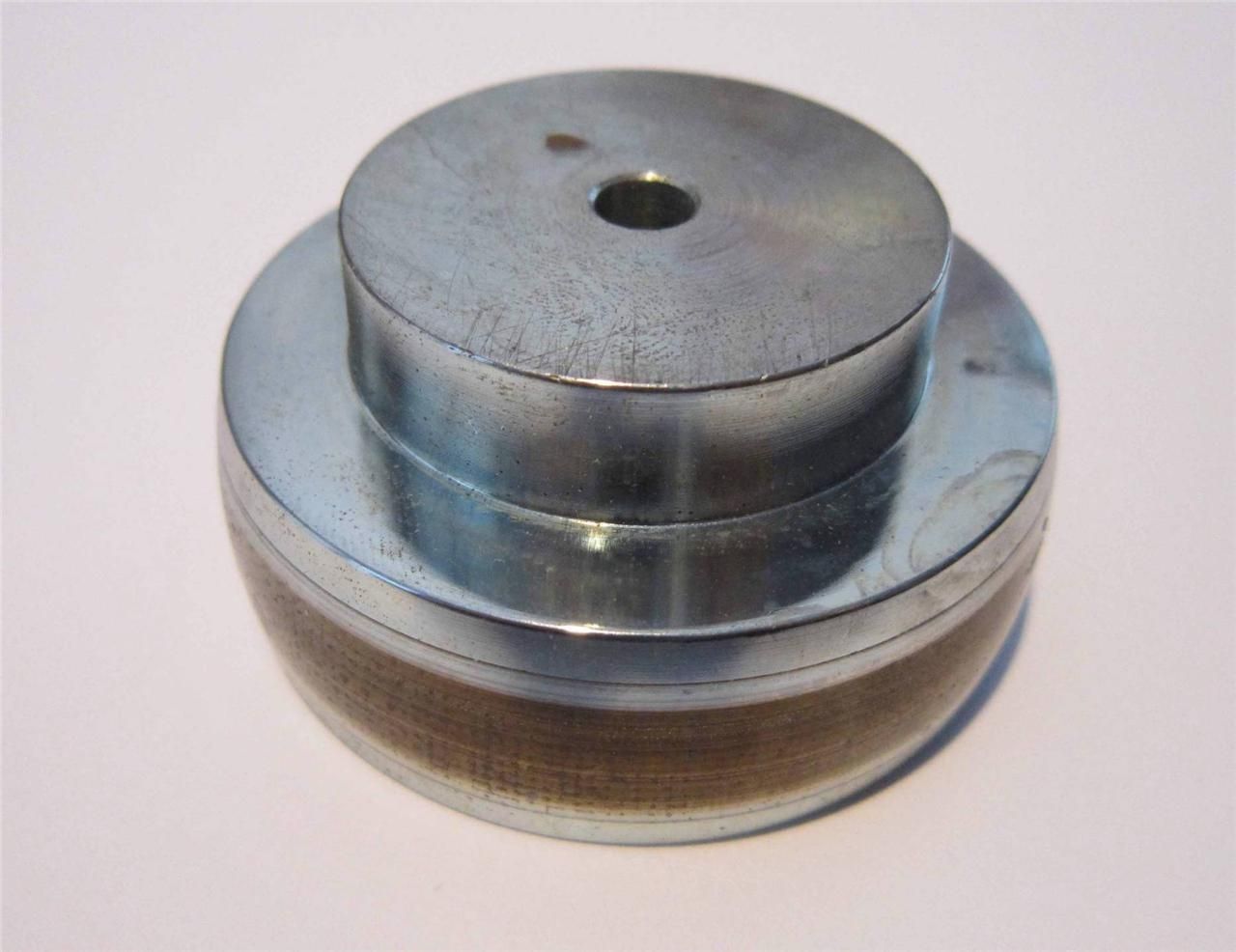
I know of no flywheels that are both specifically made for our motors and affordable. For production, the cheapest solution that I can think of is to use a cast-iron V-pulley of an appropriate size (2.5" or so?). But it would have a little more surface area, and therefore drag, than necessary. If the losses are compensated for, that shouldn't be a big deal.
I intend to try the flywheel below; it looks like it's from a reel-to-reel tape deck capstan, and weighs 458g. It cost $15 from the evil auction site. It is used, so it would not be a solution to a production run.
(An observation: The ESC actually doesn't need to be a speed control; it just needs to commutate the coils based on the sensor signals and a single enable signal. That doesn't even require a microprocessor! But I don't know if that would save any money, considering how cheap off-the-shelf ESCs are these days.)
I know of no flywheels that are both specifically made for our motors and affordable. For production, the cheapest solution that I can think of is to use a cast-iron V-pulley of an appropriate size (2.5" or so?). But it would have a little more surface area, and therefore drag, than necessary. If the losses are compensated for, that shouldn't be a big deal.
I intend to try the flywheel below; it looks like it's from a reel-to-reel tape deck capstan, and weighs 458g. It cost $15 from the evil auction site. It is used, so it would not be a solution to a production run.
11-10-2015 | 05:04 AM
#8
Thread Starter
Tech Addict
Joined: Sep 2014
Posts: 509
From: London, United Kingdom
Speedpro1 is correct, the current rating needs to be pretty high! Even a 17.5T motor on 2s LiPo will have a stall current close to 200A, and there are plenty of classes using motors much more powerful than that. But the current will only last a second or two, at the start of spool-up.
(An observation: The ESC actually doesn't need to be a speed control; it just needs to commutate the coils based on the sensor signals and a single enable signal. That doesn't even require a microprocessor! But I don't know if that would save any money, considering how cheap off-the-shelf ESCs are these days.)
I think there might be more hope in reverse-engineering the protocol of something like the TrackStar GenII 1S programming card interface.
 11-10-2015 | 05:12 AM
#9
You'd need a microprocessor to do dynamic timing advance, right? Which is really what I'm after in terms of automating the workflow (being able to set the dynamic timing advance from the computer). If it's going to be "blinky" anyway (static timing advance), using a cheap off-the-shelf ESC would be fine.
I think there might be more hope in reverse-engineering the protocol of something like the TrackStar GenII 1S programming card interface.
I think there might be more hope in reverse-engineering the protocol of something like the TrackStar GenII 1S programming card interface.
Rather than reverse-engineer the protocol for an existing ESC, it might be more cost-effective to just pay the manufacturer to do the software.
11-10-2015 | 05:44 AM
#10
Thread Starter
Tech Addict
Joined: Sep 2014
Posts: 509
From: London, United Kingdom
Also, hooking up with the Hall sensors would allow to do the same kind of "true timing advance" measurement that devices such as the G-Force/SkyRC Motor Analyzer do (which is interesting, considering the manufacturing tolerance of the timing marks!).
11-10-2015 | 07:56 AM
#11
Your comment jogged my memory: it is also possible to make a microprocessor-controlled device to put inline between the motor's Hall sensors and the ESC, to advance the timing. While that involves a little hardware, the result would be usable with any off-the-shelf ESC (eliminating supplier problems), and negates the requirement of determining anything about unknown protocols.
This sounds like a good project for Jebarus, and would definitely make his dyno much different than anything else available! It really would be neat to automatically determine the optimum timing advance curve for any particular motor. But we still need to know if there are any ESCs available that permit downloading a custom timing curve, and the format necessary to do so.
I made my own such dynamic timing module many years ago, but it was not updateable via a serial connection.
11-10-2015 | 11:37 AM
#12
Tech Master
Joined: May 2011
Posts: 1,671
From: budapest, hungary
11-12-2015 | 05:07 PM
#13
Thread Starter
Tech Addict
Joined: Sep 2014
Posts: 509
From: London, United Kingdom
How about this open source ESC? It has I2C among many other interfaces.
11-12-2015 | 05:13 PM
#14
Thread Starter
Tech Addict
Joined: Sep 2014
Posts: 509
From: London, United Kingdom
About the weight of a flywheel being too much to mount directly to the motor without support, a greater diameter flywheel of the same mass would have a similar MOI as a heavier, smaller one, right? Mass near the centre doesn't help increase the MOI as much, so you could mill it out, to make it spoked (would need to balance it after, most likely!)...
Someone with access to CNC equipment could get something quite nice...
11-13-2015 | 04:25 AM
#15
About the weight of a flywheel being too much to mount directly to the motor without support, a greater diameter flywheel of the same mass would have a similar MOI as a heavier, smaller one, right? Mass near the centre doesn't help increase the MOI as much, so you could mill it out, to make it spoked (would need to balance it after, most likely!).
Since I'm going to be using a gear drive, I can easily select the MOI that the motor sees by varying the ratio, which makes it easier to get good results with a large variation in flywheel sizes. That's important when being forced to use what's available, rather than what is optimum.
We seem to be wandering from the RC Benchmark subject of this thread, so out of courtesy to Jebarus I have started a new, generic thread.
Last edited by howardcano; 11-13-2015 at 05:03 AM.