


Control rc car with Raspberry Pi
 08-26-2015 | 07:43 AM
#1
Thread Starter
Tech Rookie
Joined: Aug 2015
Posts: 4
I'm working on a project where the goal is to be able to control a remote controlled car with a phone through WiFi. I'll be doing this by using a Raspberry Pi and a project called "pi-blaster", which enables pulse-width-modulation (PWM) on the GPIO pins of the Pi.
I have some ideas on how to use PWM to control the car, but I'm not so good when it comes to wiring and such, I'm better at the software, so I'm looking for advice in this area.
If I've understood things correctly, different voltages will result in different speeds and different "wheel angles". So if I measure that the car goes full forwards when the motor is given a voltage of 0.5V, it will go full forwards if I set the PWM of the speed pin to 0.15 (1 would be 3.3V), and if it turns full right when the servo is given a voltage of 0.3V, it will go full right if I set the PWM of the steering pin to 0.09. Is this correct or am I wrong?
I'm also wondering how I would go about to connect the PWM GPIO pins to the ESC and the steering? Would I just connect the PWM wires into the ESC and the steering instead of the signal wire?
Thanks in advance, and sorry for being a noob.
 08-26-2015 | 06:16 PM
#2
Tech Champion

Joined: Oct 2007
Posts: 7,342
It's not the voltage per se, but rather the length of time of each pulse:

The PWM signal goes to the control wire of the three wire servo plug on a servo or ESC.
There needs to be a ground connection between the ESC signal and control source. It can be through the main battery lead or servo lead ground depending on the complete system details, but be careful with ground loops for best practice, I'd try with just the battery ground first.
A couple of many sites with info. Search "RC servo signal" for lots more, image search works well too. Robotics sites might be better sources than RC, as your type of control approach is not unusual in that realm.
R/C Control Signals
Servo control interface in detail
Hope this helps.
08-27-2015 | 04:09 AM
#3
Thread Starter
Tech Rookie
Joined: Aug 2015
Posts: 4
Thanks for the answer!
I've read a fair amount about servo signals and such, but I don't quite understand it all since my knowledge of RC cars in general is pretty bad, even though I've read a fair amount about them as well.
As far as I understood, I can just replace the signal wire to the ESC and servo with the wires from the Raspberry Pi using PWM?
I've drawn a wiring scheme the shows my understanding of how to wire the car:
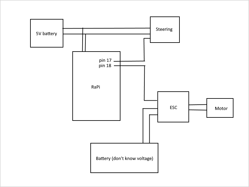
Would something like this work or am I way off?
Sorry if I sound stupid or ignorant, but I'm completely new to remote controlled vehicles, and I don't know much about them. But that's why I'm doing this project, to learn.
Thanks in advance!
I've read a fair amount about servo signals and such, but I don't quite understand it all since my knowledge of RC cars in general is pretty bad, even though I've read a fair amount about them as well.
As far as I understood, I can just replace the signal wire to the ESC and servo with the wires from the Raspberry Pi using PWM?
I've drawn a wiring scheme the shows my understanding of how to wire the car:
Would something like this work or am I way off?
Sorry if I sound stupid or ignorant, but I'm completely new to remote controlled vehicles, and I don't know much about them. But that's why I'm doing this project, to learn.
Thanks in advance!
08-27-2015 | 05:02 AM
#4
Depending on your power consumption of the PI and operating voltage you may need to provide a battery for that as well. The BEC of the ESC will be 6v and depending on the ESC specs they can supply anywhere from 1A to 3A.
Currently Active Users Viewing This Thread: 1 (0 members and 1 guests)
