


 8Likes
Lap Timing Decoder

 05-23-2016 | 08:43 AM
#617
Tech Apprentice
Joined: May 2015
Posts: 54
From: Sweden
Well, I am now one dollar closer to Hawaii too! 
I simply put a null modem adapter on the cable and suddenly:

Success!
Hmm, I don't understand the protocol. My transponder id is 6861987. How does that correspond with B237FE?
I simply put a null modem adapter on the cable and suddenly:
Success!
Hmm, I don't understand the protocol. My transponder id is 6861987. How does that correspond with B237FE?
Last edited by Barsk; 05-23-2016 at 09:01 AM.
05-23-2016 | 09:02 AM
#618
 05-23-2016 | 09:48 AM
#619
Tech Apprentice
Joined: May 2015
Posts: 54
From: Sweden
This is important to me as I have my own software that today can only read AMB RC3 protocol, but I will make it Cano compatible as well. It is built first and foremost for free practice, and has a web interface. That means you can check your times on a mobile phone as long as it has a wifi connection to the server. It is yet unreleased and work-in-progress, but already at this state fully functional. I named it Litespeed.
 05-24-2016 | 06:25 AM
#621
Tech Apprentice
Joined: May 2015
Posts: 54
From: Sweden
I think I have an explanation of why my serial communication failed in my early attempts. You are using TTL levels and not 12V levels as the standard wants. And my USB-serial adapter based on a Prolific chip seems not to enjoy that. The old XP laptop with a builtin com port works fine, but it is not where I want the Zround software. I guess I'll have to get another USB-serial adapter or patch up the design with a MAX232 serial driver chip. Hmm.
05-25-2016 | 12:31 AM
#622
I think I have an explanation of why my serial communication failed in my early attempts. You are using TTL levels and not 12V levels as the standard wants. And my USB-serial adapter based on a Prolific chip seems not to enjoy that. The old XP laptop with a builtin com port works fine, but it is not where I want the Zround software. I guess I'll have to get another USB-serial adapter or patch up the design with a MAX232 serial driver chip. Hmm.
I have done that to a few usb rs232 adaptors so that I have a low level instead that I can connect to a cpu directly. Remember the Prolific chip have an pin so you can decide the voltage of the logic level. Check data sheet.
It probably look something like below even though that is not a prolific but a FTDI chip.
 05-25-2016 | 01:54 AM
#623
Tech Apprentice
Joined: May 2015
Posts: 54
From: Sweden
EDIT: The Aten cable did not work either...
EDIT2:
Well, after a bit more of thinking I cannot come to any other conclusion that the serial comm is actually flawed in this design. It does not comply to RS-232 because of wrong levels, and it also does not comply to serial TTL communications because the signal is inverted. So using a proper USB-serial TTL cable is not going to work either. At the present state the design is up to luck if you happen to get a standard USB-serial adapter that is able to read 5 V levels where they ought to be +/- 12V. I haven't found one. If you do then all is well...
I'd like Howard to confirm or deny my findings if possible.
I have two options. Either I get a proper USB-serial TTL 5V adapter (like this one) and patch it in on the TX line before the inverter. It does not come cheap, but as a bonus I can use the +5V from USB line to power the whole decoder. All with one cable.
The other option is to use a maxim max232 chip to do conversion to standard RS-232 levels. Need to get the signal before the inverter here too. Like this.
It would be nice if someone could give some feedback to this.
Last edited by Barsk; 05-26-2016 at 12:49 AM.
05-31-2016 | 03:36 PM
#624
Tech Apprentice
Joined: May 2015
Posts: 54
From: Sweden
Hi,
I modded the decoder somewhat to incorporate an USB interface and get 5V power supply via USB as well. I used an FTDI 5V breakout USB board to accomplish it. This way the serial connection is a true 5V serial-TTL communication and there are no more problems with "incorrect" RS-232 signal levels that made my two attempts with standard USB-serial adapter cabels futile. The whole USB serial adapter stuff is now hidden inside the decoder box and has a cable sticking out.
To make this the the RX connector from the FTDI board need to be soldered directly to pin2 of U62 (as seen in the picture). The +5V go to the voltage regulator output pin pad. I removed the voltage regulator and diod which is now obsolete. Ground goes to same pad as before. There are only three connectors used on the FTDI board. The old serial out cables that was attached to the DB9 connector can be removed.
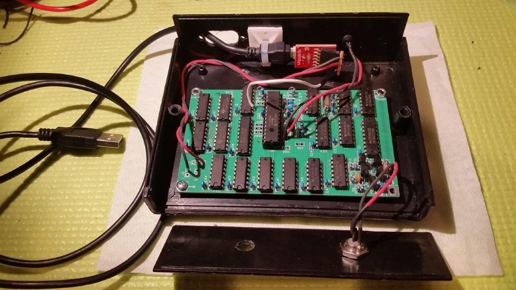
The computer need to install the FTDI drivers, which is on Windows update, so it is a smooth ride. At least on win 7/8/10. When the USB is attached the power comes on immediately on the decoder, but the COM port need to initialize itself first so the copyright message on startup gets lost unfortunately. One can fix that with a power switch or reset button. Or just simply cycle power to the decoder (internally in the box) while still having the usb cable attached. Works well for a quick test to verify.
Quite simple mod really. Now the box have only two cables - USB and coax.
I modded the decoder somewhat to incorporate an USB interface and get 5V power supply via USB as well. I used an FTDI 5V breakout USB board to accomplish it. This way the serial connection is a true 5V serial-TTL communication and there are no more problems with "incorrect" RS-232 signal levels that made my two attempts with standard USB-serial adapter cabels futile. The whole USB serial adapter stuff is now hidden inside the decoder box and has a cable sticking out.
To make this the the RX connector from the FTDI board need to be soldered directly to pin2 of U62 (as seen in the picture). The +5V go to the voltage regulator output pin pad. I removed the voltage regulator and diod which is now obsolete. Ground goes to same pad as before. There are only three connectors used on the FTDI board. The old serial out cables that was attached to the DB9 connector can be removed.
The computer need to install the FTDI drivers, which is on Windows update, so it is a smooth ride. At least on win 7/8/10. When the USB is attached the power comes on immediately on the decoder, but the COM port need to initialize itself first so the copyright message on startup gets lost unfortunately. One can fix that with a power switch or reset button. Or just simply cycle power to the decoder (internally in the box) while still having the usb cable attached. Works well for a quick test to verify.
Quite simple mod really. Now the box have only two cables - USB and coax.
06-01-2016 | 12:36 AM
#626
Tech Apprentice
Joined: May 2015
Posts: 54
From: Sweden

there are a number of options to the breakout board I used, just take care to use a 5V version (not 3.3V). Actually I thought it had mounting holes on each side so that I could fit it properly to the chassis- and not have to use an attached cable. When I got the board it turned out there were no holes...
As I know you have already a USB connector on your casing I would probably use that and wire it directly to the usb pads on the FTDI board. Or something like this would make a nice solution. Note that the Sparkfun board I used have a mini connector though.
06-22-2016 | 01:52 AM
#627
Tech Apprentice
Joined: May 2015
Posts: 54
From: Sweden
I was looking through the schematics and it looks like the full "raw" bitstream, or even the full bytes is available to the microprocessor. There is as I understand it a sync made from the preamble detector that tells the processor when the first byte(s) after the preamble is availabe, and that is (maybe?) the only part of data that is decoded? But are the other parts of the transmission readable too?
Why I am asking is because I am thinking of swapping out the current microprocessor for another - with some code to be used to capture the full data records of the transmission. If the hardware as-is can be used to capture the whole transmission then it is just a matter of software to transmit that on the serial bus. Another program on the PC side could then write it down to a file in a format readable by a PIC compiler, or even in a format identical to the transponder example program that Howard has shared. If that works one could "easily" clone any transponder by compiling a new hex file and burn that to a PIC processor.
Just hypothetical at this stage, but if the hardware can be used as a raw capture device, without modifications, then it is just a matter of software!
06-22-2016 | 04:21 AM
#628
I was looking through the schematics and it looks like the full "raw" bitstream, or even the full bytes is available to the microprocessor. There is as I understand it a sync made from the preamble detector that tells the processor when the first byte(s) after the preamble is availabe, and that is (maybe?) the only part of data that is decoded? But are the other parts of the transmission readable too?
Why I am asking is because I am thinking of swapping out the current microprocessor for another - with some code to be used to capture the full data records of the transmission. If the hardware as-is can be used to capture the whole transmission then it is just a matter of software to transmit that on the serial bus. Another program on the PC side could then write it down to a file in a format readable by a PIC compiler, or even in a format identical to the transponder example program that Howard has shared. If that works one could "easily" clone any transponder by compiling a new hex file and burn that to a PIC processor.
Just hypothetical at this stage, but if the hardware can be used as a raw capture device, without modifications, then it is just a matter of software!
Why I am asking is because I am thinking of swapping out the current microprocessor for another - with some code to be used to capture the full data records of the transmission. If the hardware as-is can be used to capture the whole transmission then it is just a matter of software to transmit that on the serial bus. Another program on the PC side could then write it down to a file in a format readable by a PIC compiler, or even in a format identical to the transponder example program that Howard has shared. If that works one could "easily" clone any transponder by compiling a new hex file and burn that to a PIC processor.
Just hypothetical at this stage, but if the hardware can be used as a raw capture device, without modifications, then it is just a matter of software!
But that still doesn't guarantee that the transponders would be recognized by any decoder. The transponders I cloned work on my decoder and the RC3, but not the RC4. I still don't know why, but if you find out, please let us know!
06-23-2016 | 12:23 AM
#629
Tech Apprentice
Joined: May 2015
Posts: 54
From: Sweden
Wow. I backwards engineered my way into the same thought patterns as you, Howard. That's cool.
Ok, nice to know the HW works for cloning the way I thought. It would be interesting to find out what the transponder records are and to fully decode them. At least the "passing" records. Was Payalneg on that? I remember some cryptical post about convolutional code and verbiti alghorithms...
But that does not answer the question why a full clone would not work on a RC4 decoder. Obviously something is missing.
06-23-2016 | 09:05 AM
#630
Wow. I backwards engineered my way into the same thought patterns as you, Howard. That's cool.
Ok, nice to know the HW works for cloning the way I thought. It would be interesting to find out what the transponder records are and to fully decode them. At least the "passing" records. Was Payalneg on that? I remember some cryptical post about convolutional code and verbiti alghorithms...
But that does not answer the question why a full clone would not work on a RC4 decoder. Obviously something is missing.
Ok, nice to know the HW works for cloning the way I thought. It would be interesting to find out what the transponder records are and to fully decode them. At least the "passing" records. Was Payalneg on that? I remember some cryptical post about convolutional code and verbiti alghorithms...
But that does not answer the question why a full clone would not work on a RC4 decoder. Obviously something is missing.