


Motor Winding Length
 12-11-2012 | 01:49 AM
#1
Hey guys, I've got an oddball question. On a motor, like the 13T Hobbywing, where the wires sticking out of the can are technically part of the motor windings, thus contributing to the length of the winding, would cutting those wires closer to the can have any effect??
Here's an example: A motor comes out of the box with 4" of (heavy copper winding) wire sticking out of it. An individual cuts that wire shorter and attaches it directly to the ESC. Does it have any effect on motor speed or torque?
I know there is some natural resistance in any wire, but given that we're talking about such a short length I'm curious if there is any effect on output.
The next natural question is whether or not a sanctioning body would consider this modification of the motor, given that these are integral and not a removable item.
Thoughts?
Jim
Last edited by monkeyracing; 12-13-2012 at 03:37 PM. Reason: S
 12-11-2012 | 06:49 AM
#3
I'll assume that the wire leads are the same gauge as the winding-- actually, the same piece of wire (or wires, if wound in parallel). If so, making them shorter would increase performance. The length of wire in the windings for 13 turns is relatively short. If you can decrease the total wire length by, say, 3% by removing the excess leads, then you'll get a 3% increase in torque and power due to the lower resistance (with everything else being equal). There will be no significant change in the RPM.
You don't need to attach the remaining leads directly to the ESC as long as you use much heavier wire in place of the lead length that was removed.
You don't need to attach the remaining leads directly to the ESC as long as you use much heavier wire in place of the lead length that was removed.
Last edited by howardcano; 12-11-2012 at 07:49 AM.
12-11-2012 | 09:56 AM
#4
Thanks for the replies. You are correct in assuming the wires and the windings are one and the same. We have had a few people shorten the wires on their motors and solder direct to the ESC. This is a very spec class, btw. I suspected that the extra length of winding, even outside the can, would have a different effect than an equal length of power wire.
We're not seeing any big differences in performance, that I'm aware of, but I suppose a dyno test is in order.
We're not seeing any big differences in performance, that I'm aware of, but I suppose a dyno test is in order.
12-11-2012 | 10:39 AM
#6
Anywhere from 2"-4". Probably not enough to make much of a difference. The specific motor in question is a 380 size, probably around 17 turn. There will be several/many/a-whole-bunch of wire in there, I would guess.
12-11-2012 | 11:11 AM
#7
Do you have a milliohmmeter you can use to measure the resistance? This will give you an accurate number for the increased torque/power you'll get from shortening the motor leads.
Or you can sacrifice a motor, unwind it, and measure the winding length.
I don't think there's much winding wire length on a 17 turn 380!
Or you can sacrifice a motor, unwind it, and measure the winding length.
I don't think there's much winding wire length on a 17 turn 380!
Last edited by howardcano; 12-11-2012 at 11:44 AM.
12-11-2012 | 03:18 PM
#9
Tech Champion

Joined: Oct 2007
Posts: 7,342
The length of wire outside of the motor is vastly different than the most of the length inside the motor. The key word being overlooked is windings. When wire is wound it creates inductance. The inductance becomes more important as RPM increases, quickly becomes far more important than resistance.
The direct relationship previously suggested is only true at stall. Once the motor starts turning the difference will decrease fairly rapidly. Correct that at high RPM will be the smallest difference. Overall I suspect the difference will fairly small, as you've noted in your performance observations.
It is desirable to limit the ESC to motor wiring length. Just don�t over do it, leave a little slack for chassis flex, servicing, etc.
12-12-2012 | 01:11 AM
#10
The relationship is valid at all speeds. Torque in a permanent magnet DC motor is directly proportional to current. The current is inversely proportional to resistance. At any given speed, reducing the resistance will increase the torque and power in inverse proportion to the change in resistance.
There is a small deviation in this behavior, in that some amount of current is always necessary to operate the motor, even with no load. This is due to frictional and hysteresis losses. For the purposes of our conversation they can be ignored.
The inductance affects the commutation timing required for optimum operation. Inductance has much less effect than resistance on output power, since it is reactive, and therefore lossless.
Last edited by howardcano; 12-12-2012 at 02:39 AM.
12-12-2012 | 09:32 PM
#11
Tech Champion
Joined: Oct 2007
Posts: 7,342
Consider a typical dyno chart. Isn’t the current dropping off as RPMs increase because the inductance portion of the impedance increases as switching frequency goes up with RPM? Yes inductance is lossless, isn’t that why efficiency goes up, as the lossless inductance becomes more significant relative to the resistance based losses? If the resistance losses are a smaller portion wouldn’t resistance improvements also be a smaller portion of the overall?
I tried a few examples to check.
Assume an ideal 8V source, initial low RPM amps of 100, 20A at high RPM. Start with a lead resistance of 1mohm (roughly 4” of 14awg). Then cut the lead resistance by 75%.
Low RPM:
8V, 100A, 1mohm lead resistance, voltage drops to 7.9
0.25mohm, amperage increases to ~100.946, voltage drop to ~7.975
About 1.90% power increase
High RPM:
8V, 20A, 1mohm, voltage drops to 7.98
0.25mohm, amperage increases to ~20.038, voltage drops to ~7.995
About 0.376% power increase
An improvement, yes, never a question. I’m just not sure it’s constant with RPM. Have I gone astray or missed something?
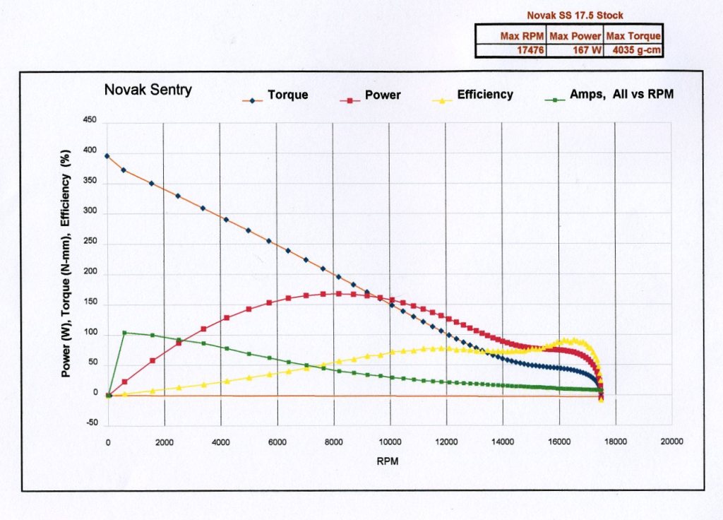
Chart credit to John Stranahan.
I tried a few examples to check.
Assume an ideal 8V source, initial low RPM amps of 100, 20A at high RPM. Start with a lead resistance of 1mohm (roughly 4” of 14awg). Then cut the lead resistance by 75%.
Low RPM:
8V, 100A, 1mohm lead resistance, voltage drops to 7.9
0.25mohm, amperage increases to ~100.946, voltage drop to ~7.975
About 1.90% power increase
High RPM:
8V, 20A, 1mohm, voltage drops to 7.98
0.25mohm, amperage increases to ~20.038, voltage drops to ~7.995
About 0.376% power increase
An improvement, yes, never a question. I’m just not sure it’s constant with RPM. Have I gone astray or missed something?
Chart credit to John Stranahan.
12-13-2012 | 06:31 AM
#12
Your calculations didn't include the internal resistance of the motor windings. The resistance in the motor leads must be added to this. The motor in the example dyno results you gave has an internal resistance of about 75 milliohms (8V divided by about 107A at stall, extrapolated from the plot). In this case, decreasing the lead resistance from 1 milliohm to 0.25 milliohm only gives a 1% change in total resistance.
Also, your calculations are for input power, not motor output power.
Thank you for your posts! It's obvious we both enjoy the technical aspect of our hobby. Maybe most guys aren't interested, but for us, its the FUN part!
 12-17-2012 | 07:55 PM
#15
Tech Champion
Joined: Oct 2007
Posts: 7,342
The current decreases with increasing motor speed because the back EMF increases. (The back EMF of a motor is given by its KV constant times its rotational speed.) This happens even if there is no inductance. Likewise, the efficiency peaks at a higher speed than the power output even with no inductance. (You can see this effect with some simple calculations, but I won't give an example here so as to not clutter up the thread.)
Your calculations didn't include the internal resistance of the motor windings. The resistance in the motor leads must be added to this. The motor in the example dyno results you gave has an internal resistance of about 75 milliohms (8V divided by about 107A at stall, extrapolated from the plot). In this case, decreasing the lead resistance from 1 milliohm to 0.25 milliohm only gives a 1% change in total resistance.
Also, your calculations are for input power, not motor output power.
Thank you for your posts! It's obvious we both enjoy the technical aspect of our hobby. Maybe most guys aren't interested, but for us, its the FUN part!
Correct, my calculations did not include any impedance (complex resistance) in the motor windings. I treated it as a constant as there is not any change, unless one opens up the motor and rewinds it like we used to do back in the day. I just extrapolated from the posted dyno data for the examples.
Yes, I calculated the input power to the motor. I presumed that the relatively small changes would have minimal impact on the motor efficiency. More power in would equal more power out.
No problem, it comes pretty naturally. At least it pays the bills.

Cheers
Last edited by Dave H; 12-18-2012 at 12:19 AM.